G424 Service Manual Base Engine Service Procedure159
7EN0452
6EN0549
9EN0072
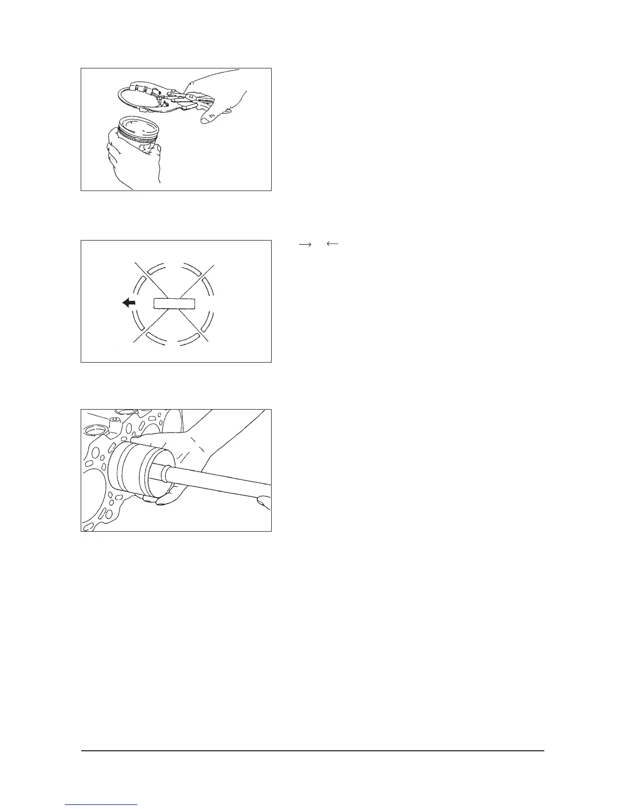
(2) Using piston ring expander, fit No.2 and then No.1 piston
ring into position.
NOTE: Install piston ring with identification mark facing up,
to the piston crown
(3) Install the No.1 piston ring in the same manner as
step 2.
D Piston and connecting rod installation
(1) Liberally coat engine oil on the circumference of the
piston, piston ring, and oil ring.
(2) Arrange the piston ring and oil ring gaps (side rail and
spacer) as shown in the illustration.
(3) Insert the piston and connecting rod assembly from
above the cylinder in such a way that the front
mark(arrow) on the top of the piston will be directed
toward the camshaft sprocket.
(4) Insert the piston and connecting rod assembly with the
piston rings held firmly with a ring band. Forcing it by
pounding should be avoided because damage to the
piston rings or crank pin could result.
Upper
side
rail
Lower side
ral
Piston pin
No.1
No.2 ring gap
and space gap
 Loading...