4-54 Inspection, Maintenance and Adjustment 022-00028AE Operation and Maintenance Manual
CONTROL LEVER ACTIVATION PRESSURE
(S/N 1001 thru 2000 Europe Low Noise
Kit)
(S/N 2001 and Up)
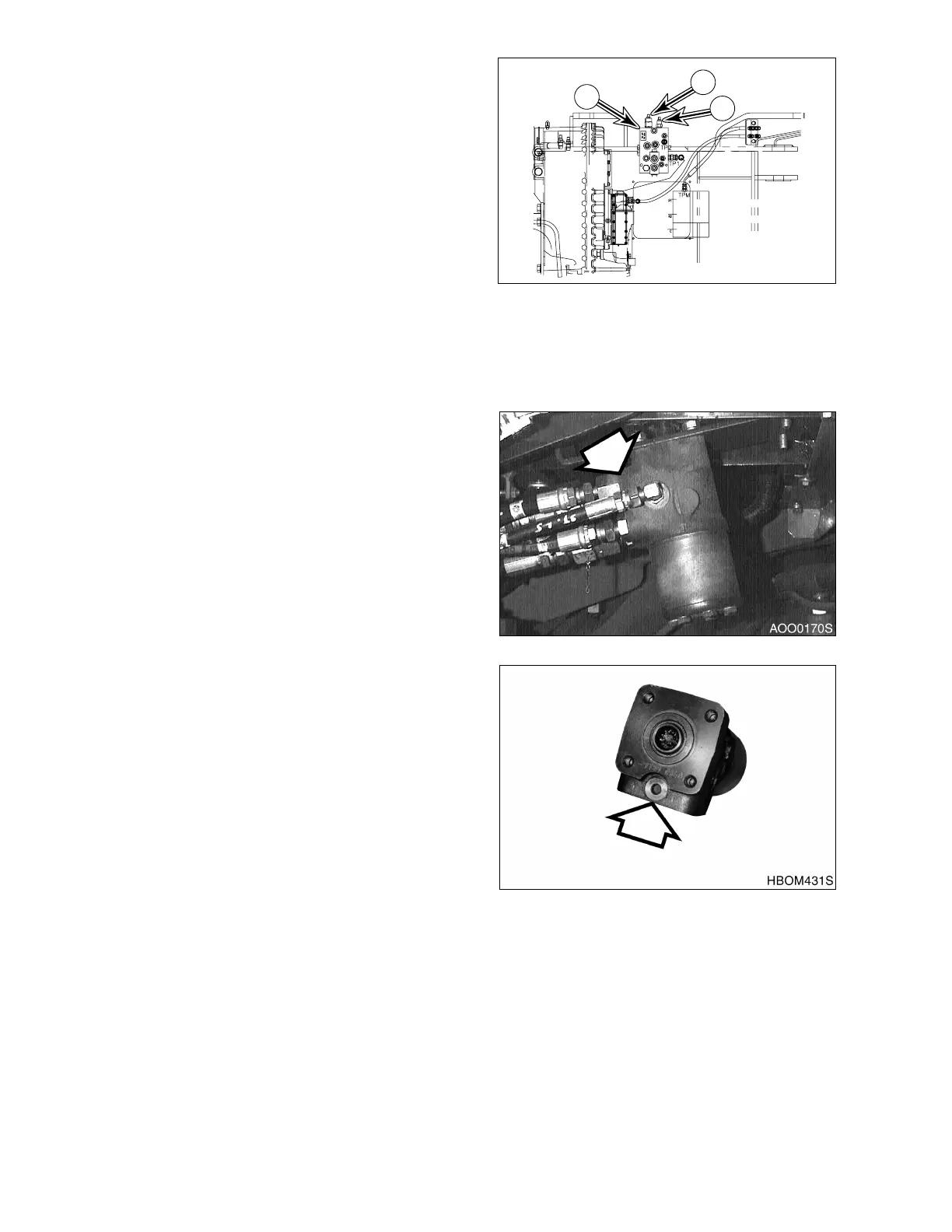
1. Attach gauge to port (2, Figure 93).
2. Adjust relief cartridge (3, Figure 96) on
brake and pilot and fan motor supply valve
(1, Figure 96). Relief pressure should be
set at 28 kg/cm
2
(398 psi).
3. Loosen lock nut on adjusting screw. Turn
adjusting screw clockwise to raise relief
pressure. Turn adjusting screw
counterclockwise to lower relief pressure.
4. Tighten lock nut after adjustment has been
made.
STEERING PUMP PRESSURE
1. Attach gauge to port (3, Figure 93).
2. Adjust relief valve cartridge on steering
valve (Figure 97). Cartridge must be
adjusted to open at 200 ±5 kg/cm
2
(2,845
±70 psi).
3. Unscrew remove plug and washer. Adjust
screw that is beneath plug. Turn screw
clockwise to raise relief pressure. Turn
screw counterclockwise to lower relief
pressure.
4. Install plug and washer after pressure has
been adjusted.
TRANSMISSION CLUTCH PRESSURE
1. Attach gauge to port (4, Figure 93)
2. It is not impossible to adjust pressure.
• Transmission clutch pressure: 16 kg/cm
2
(228 psi)
APO0140L
1
3
2
Figure 96
+3
-2
+43
-30
Figure 97
Figure 98
+2
0
+28
0