14
Press [Setting] for more than 6 seconds, enter the password set during initialization, Step 3
and click [OK].
Click [Network].
Step 4
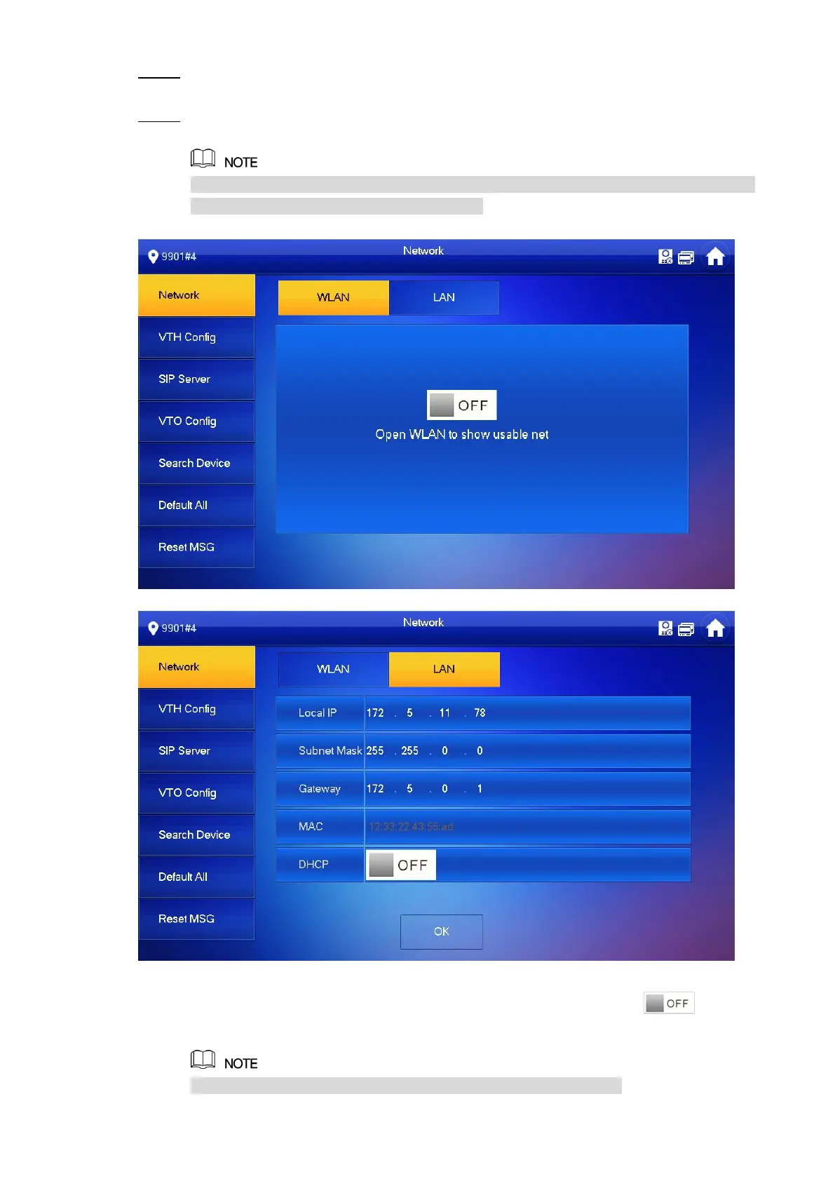
The system displays “Network” interface, as shown in Figure 2-12 or Figure 2-13.
IP addresses of VTH and VTO shall be in the same network segment. Otherwise, VTH
will fail to obtain VTO info after configuration.
Network (1) Figure 2-12
Network (2) Figure 2-13
LAN
Enter “Local IP”, “Subnet Mask” and “Gateway”, press [OK]. Or press to enable
DHCP function and obtain IP info automatically.
If the device has WLAN function, please click “WLAN” tab to set it.
 Loading...