6 | Application guidelines
Installer reference guide
46
EPRA08~12EAV3+W1 + ETBH/X12EF6V+9W
Daikin Altherma 3 H MT W
4P634885-1 – 2021.03
▪ For the additional zone:
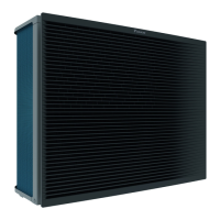
- The heat pump convectors are connected as follows: Warm water → Indoor
unit; Cold water → Outdoor unit
- The desired room temperature is set via the controller of the heat pump
convectors. There are different controllers and setups possible for the heat
pump convectors. For more information, see:
The installation manual of the heat pump convectors
The installation manual of the heat pump convector options
The addendum book for optional equipment
- The heating or cooling demand signals of each heat pump convector are
connected in parallel to the digital input on the indoor unit (X2M/35a and
X2M/30). The indoor unit will only supply the desired additional leaving water
temperature when there is an actual demand.
▪ The user interface integrated in the indoor unit decides the space operation
mode. Mind that the operation mode on each controller of the heat pump
convectors must be set to match the indoor unit.
Configuration
Setting Value
Unit temperature control:
▪ #: [2.9]
▪ Code: [C‑07]
2 (Room thermostat): Unit operation
is decided based on the ambient
temperature of the dedicated Human
Comfort Interface.
Note:
▪ Main room = dedicated Human
Comfort Interface used as room
thermostat functionality
▪ Other rooms = external room
thermostat functionality
Number of water temperature zones:
▪ #: [4.4]
▪ Code: [7‑02]
1 (Dual zone): Main + additional
In case of heatpump convectors:
External room thermostat for the
additional zone:
▪ #: [3.A]
▪ Code: [C‑06]
1 (1 contact): When the used
external room thermostat or heatpump
convector can only send a thermo ON/
OFF condition. No separation between
heating or cooling demand.
Bizone kit installed:
▪ #: [9.P.1]
▪ Code: [E‑0B]
2 (Yes): A bizone kit is installed in order
to add an additional temperature zone.
 Loading...
