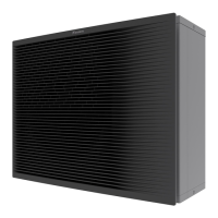
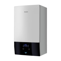
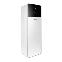
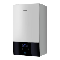
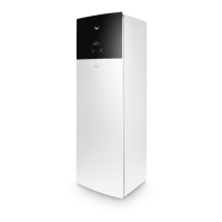
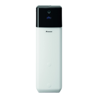
ESIE09-08B Functional Parts Layout
Refrigerant Circuit 19
Bird’s-eye view
Legend
21
22
23
24
A
28
27
26
25
C
B
D
7
No. Name No. Name
1 High pressure sensor 18 Refrigerant liquid connection R-410A
2 High pressure switch 19 Refrigerant gas connection R-410A
3 Compressor R-134a 20 Return water connection from tank
4 Outlet water connection 21 Low pressure sensor
5 Inlet water connection 22 4-way valve (R-134a)
6 Filter 23 Accumulator R-134a
7 Solenoid valve 24 Drain
8 Expansion vessel 12 l 25 Electronic expansion valve R-134a
9 DC inverter pump 26 Electronic expansion valve R-410A
10 Pressure relief valve 27 Refrigerant gas connection R-410A
11 Manometer 28 Refrigerant liquid connection R-410A
12 High pressure service port R-134a A R6T Discharge thermistor
13 Low pressure service port R-134a B R7T Liquid thermistor R-134a
14 Heat exchanger: refrigerant - water C R3T Liquid thermistor R-410A
15 Heat exchanger: refrigerant - refrigerant D R4T Returning water thermistor
16 (Q2L) Thermal protector water piping E R5T Leaving water thermistor
17 Air purge valve
 Loading...
