24
evacuate excess concentration. If a Zone Control system
Accessory PCB to ensure that the Zoning Dampers open
during mitigation mode to provide ventilation throughout
information concerning mitigation mode. Once sensors
resume its normal operation. If the sensors detect another
WARNING
NOTE:
NOTE:
Single Stage Cooling Application: Refer to the Design
Two-Stage Cooling Application:
1. Purge gauge lines. Connect service gauge manifold
2. Temporarily install thermometer on liquid (small) line
3.
NOTE: To adjust superheat, turn the valve stem
clockwise to increase and counterclockwise to
decrease. Refer to TXV Superheat Adjustment
referenced in this manual.
NOTE: Do NOT adjust the charge based on
suction pressure unless there is a gross
undercharge. If an under charge is suspected,
recover the charge, re-evacuate the system,
and recharge per data plate. No adjustments
should be made if suspecting a charge issue.
4. Disconnect manifold set, installation is complete.
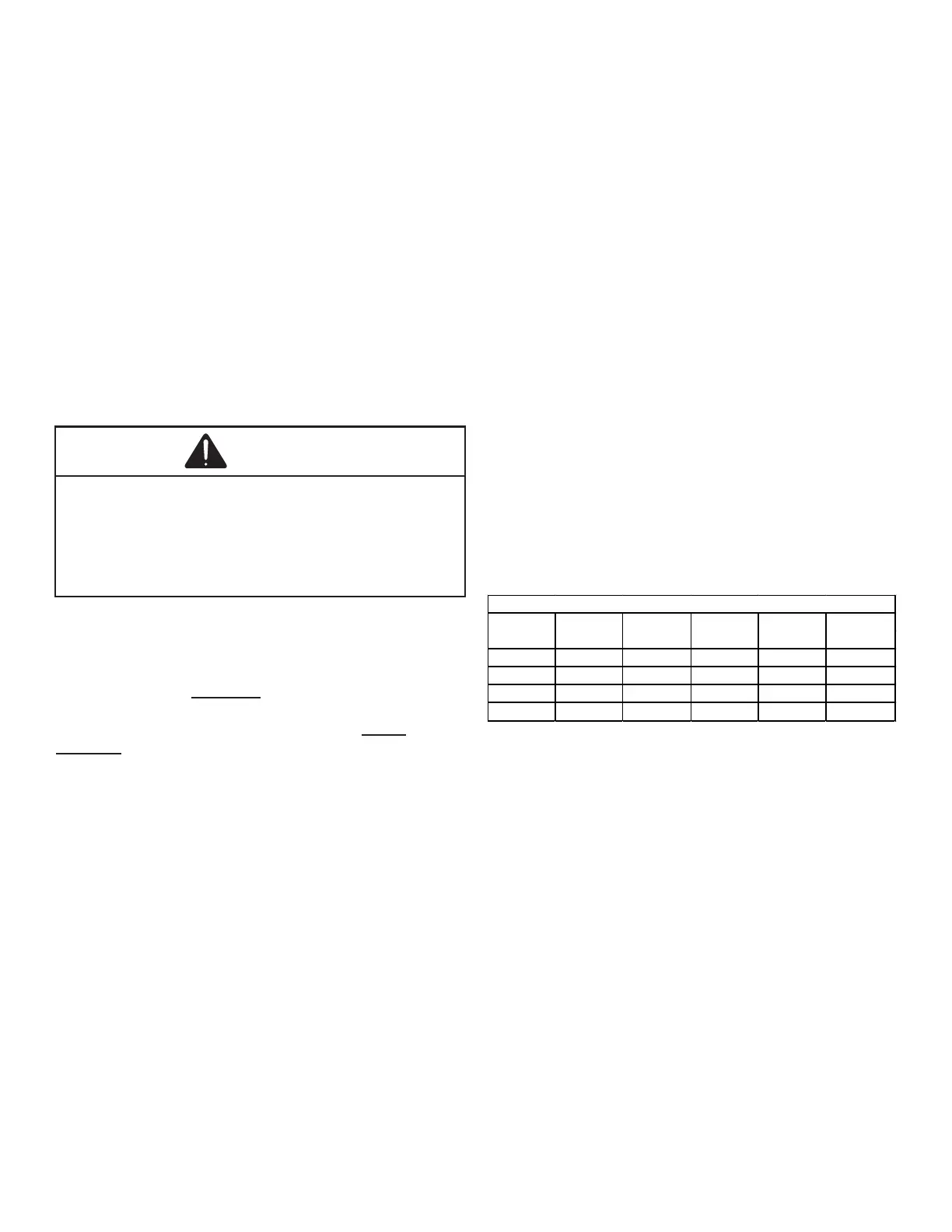
DHG036 15-17 2-4 TXV Low 82
DHG048 16-17 2-4 TXV Low 82
DHG060 14-17 5-7 TXV Low 82
DHG072 14-18 7-11 TXV Low 82
Design Superheat & Subcooling
1.
Test/Balance Menu to force the unit to OFF MODE.
2. Inspect all registers and set them to the normal open
position.
3. Turn on the electrical supply at the disconnect.
4.
DDC controls installed, use Test/Balance Menu to
internal delays.
5.
DDC controls installed, use Test/Balance Menu to
internal delays.