6 Electrical installation
Installation manual
22
EBLA09~16D + EDLA09~16D
Daikin Altherma 3 M
4P620239-1B – 2022.05
Item Description
Room thermostat
(wired or wireless)
In case of wireless room
thermostat, see:
▪ Installation manual of the wireless
room thermostat
▪ Addendum book for optional
equipment
In case of wired room thermostat
without multi-zoning base unit, see:
▪ Installation manual of the wired
room thermostat
▪ Addendum book for optional
equipment
In case of wired room thermostat
with multi-zoning base unit, see:
▪ Installation manual of the wired
room thermostat (digital or
analogue) + multi-zoning base unit
▪ Addendum book for optional
equipment
▪ In this case:
▪ You need to connect the wired
room thermostat (digital or
analogue) to the multi-zoning
base unit
▪ You need to connect the multi-
zoning base unit to the outdoor
unit
▪ For cooling/heating operation,
you also need to implement a
relay (field supply, see
addendum book for optional
equipment)
Wires: 0.75mm²
Maximum running current: 100mA
For the main zone:
▪ [2.9] Control
▪ [2.A] Ext thermostat type
For the additional zone:
▪ [3.A] Ext thermostat type
▪ [3.9] (read-only) Control
Item Description
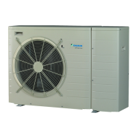
Heat pump convector There are different controllers and
setups possible for the heat pump
convectors.
Depending on the setup, you also
need to implement a relay (field
supply, see addendum book for
optional equipment).
For more information, see:
▪ Installation manual of the heat
pump convectors
▪ Installation manual of the heat
pump convector options
▪ Addendum book for optional
equipment
Wires: 0.75mm²
Maximum running current: 100mA
For the main zone:
▪ [2.9] Control
▪ [2.A] Ext thermostat type
For the additional zone:
▪ [3.A] Ext thermostat type
▪ [3.9] (read-only) Control
Remote outdoor
sensor
See:
▪ Installation manual of the remote
outdoor sensor
▪ Addendum book for optional
equipment
Wires: 2×0.75mm²
[9.B.1]=1 (External sensor =
Outdoor)
[9.B.2] Ext. amb. sensor offset
[9.B.3] Averaging time
Remote indoor sensor See:
▪ Installation manual of the remote
indoor sensor
▪ Addendum book for optional
equipment
Wires: 2×0.75mm²
[9.B.1]=2 (External sensor = Room)
[1.7] Room sensor offset
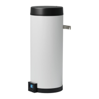
Human Comfort
Interface
See:
▪ Installation and operation manual of
the Human Comfort Interface
▪ Addendum book for optional
equipment
Wires: 2×(0.75~1.25mm²)
Maximum length: 500m
[2.9] Control
[1.6] Room sensor offset