8 Configuration
Installation manual
38
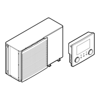
EBLA09~16D + EDLA09~16D
Daikin Altherma 3 M
4P620239-1B – 2022.05
NOTICE
If there are 2 zones and the emitter types are wrongly
configured, water of high temperature can be sent towards
a low temperature emitter (underfloor heating). To avoid
this:
▪ Install an aquastat/thermostatic valve to avoid too high
temperatures towards a low temperature emitter.
▪ Make sure you set the emitter types for the main zone
[2.7] and for the additional zone [3.7] correctly in
accordance with the connected emitter.
NOTICE
An overpressure bypass valve can be integrated in the
system. Keep in mind that this valve might not be shown
on the illustrations.
Glycol Filled system
This setting gives the installer the possibility to indicate whether the
system is filled with glycol or water. This is important in case glycol is
used to protect the water circuit against freezing. If NOT set
correctly, the liquid in the piping can freeze.
# Code Description
N/A [E-0D] Glycol Filled system: Is the system
filled with glycol?
▪ 0: No
▪ 1: Yes
NOTICE
If you add glycol to the water, you also need to install a
flow switch (EKFLSW1).
Capacity / Booster heater capacity
The capacity of the booster heater must be set for the energy
metering and/or power consumption control feature to work properly.
When measuring the resistance value of the booster heater, you can
set the exact heater capacity and this will lead to more accurate
energy data.
# Code Description
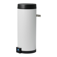
[9.4.1] [6-02] Capacity / Booster heater capacity
[kW]. Only applies to domestic hot water
tank with an internal booster heater. The
capacity of the booster heater at nominal
voltage.
Range: 0~10kW
8.2.4 Configuration wizard: Backup heater
INFORMATION
▪ For models with integrated backup heater (3V models),
most of the backup heater settings are fixed.
▪ For other models, the backup heater settings are only
applicable in case the optional external backup heater
kit is installed.
The backup heater is adapted to be connected to most common
European electricity grids. If the backup heater is available, the
voltage, configuration and capacity must be set on the user
interface.
The capacities for the different steps of the backup heater must be
set for the energy metering and/or power consumption control
feature to work properly. When measuring the resistance value of
each heater, you can set the exact heater capacity and this will lead
to more accurate energy data.
Backup heater type
▪ For models with integrated backup heater, this is fixed to 3V.
▪ For other models, this can be set to No heater, or External
heater (i.e. when the optional external backup heater kit is
installed).
# Code Description
[9.3.1] [E‑03] ▪ 0: No heater
▪ 1: External heater
▪ 2: 3V
Voltage
▪ For a 3V model, this is fixed to 230V, 1ph.
▪ The optional external backup heater can be set to 230V, 1ph or
400V, 3ph.
# Code Description
[9.3.2] [5‑0D] ▪ 0: 230V, 1ph
▪ 2: 400V, 3ph
Configuration
The backup heater can be configured in different ways. It can be
chosen to have a 1-step only backup heater or a backup heater with
2 steps. If 2 steps, the capacity of the second step depends on this
setting. It can also be chosen to have a higher capacity of the
second step in emergency.
▪ For a 3V model, this is fixed to Relay1.
▪ The optional external backup heater can be set to the following:
# Code Description
[9.3.3] [4‑0A] ▪ 0: Relay 1
▪ 1: Relay 1 / Relay 1+2
▪ 2: Relay 1 / Relay 2
▪ 3: Relay 1 / Relay 2 Emergency Relay
1+2
INFORMATION
Settings [9.3.3] and [9.3.5] are linked. Changing one
setting influences the other. If you change one, check if the
other is still as expected.
INFORMATION
During normal operation, the capacity of the second step of
the backup heater at nominal voltage is equal to
[6‑03]+[6‑04].
INFORMATION
If [4‑0A]=3 and emergency mode is active, the power
usage of the backup heater is maximal and equal to
2×[6‑03]+[6‑04].
Capacity step 1
# Code Description
[9.3.4] [6‑03] ▪ The capacity of the first step of the
backup heater at nominal voltage.
Additional capacity step 2
Restriction: Only applicable in case the external backup heater kit
is installed.
# Code Description
[9.3.5] [6‑04] ▪ The capacity difference between the
second and first step of the backup
heater at nominal voltage. Nominal
value depends on backup heater
configuration.