6 Electrical installation
Installation manual
23
EBLA09~16D + EDLA09~16D
Daikin Altherma 3 M
4P620239-1B – 2022.05
Item Description
(in case of DHW tank)
3‑way valve
See:
▪ Installation manual of the 3-way
valve
▪ Addendum book for optional
equipment
Wires: 3×0.75mm²
Maximum running current: 100mA
[9.2] Domestic hot water
(in case of DHW tank)
Domestic hot water
tank thermistor
See:
▪ Installation manual of the domestic
hot water tank
▪ Addendum book for optional
equipment
Wires: 2
The thermistor and connection wire
(12m) are delivered with the domestic
hot water tank.
[9.2] Domestic hot water
(in case of DHW tank)
Power supply for
booster heater (from
outdoor unit to thermal
protector of booster
heater)
See:
▪ Installation manual of the domestic
hot water tank
▪ Addendum book for optional
equipment
Wires: (2+GND)×2.5mm²
[9.4] Booster heater
(in case of DHW tank)
Power supply for
booster heater (from
mains to outdoor unit)
See:
▪ Installation manual of the domestic
hot water tank
▪ Addendum book for optional
equipment
Wires: 2+GND
Maximum running current: 13A
[9.4] Booster heater
WLAN cartridge See:
▪ Installation manual of the WLAN
cartridge
▪ Installer reference guide
—
[D] Wireless gateway
Flow switch See installation manual of the flow
switch
Wires: 2×0.5mm²
—
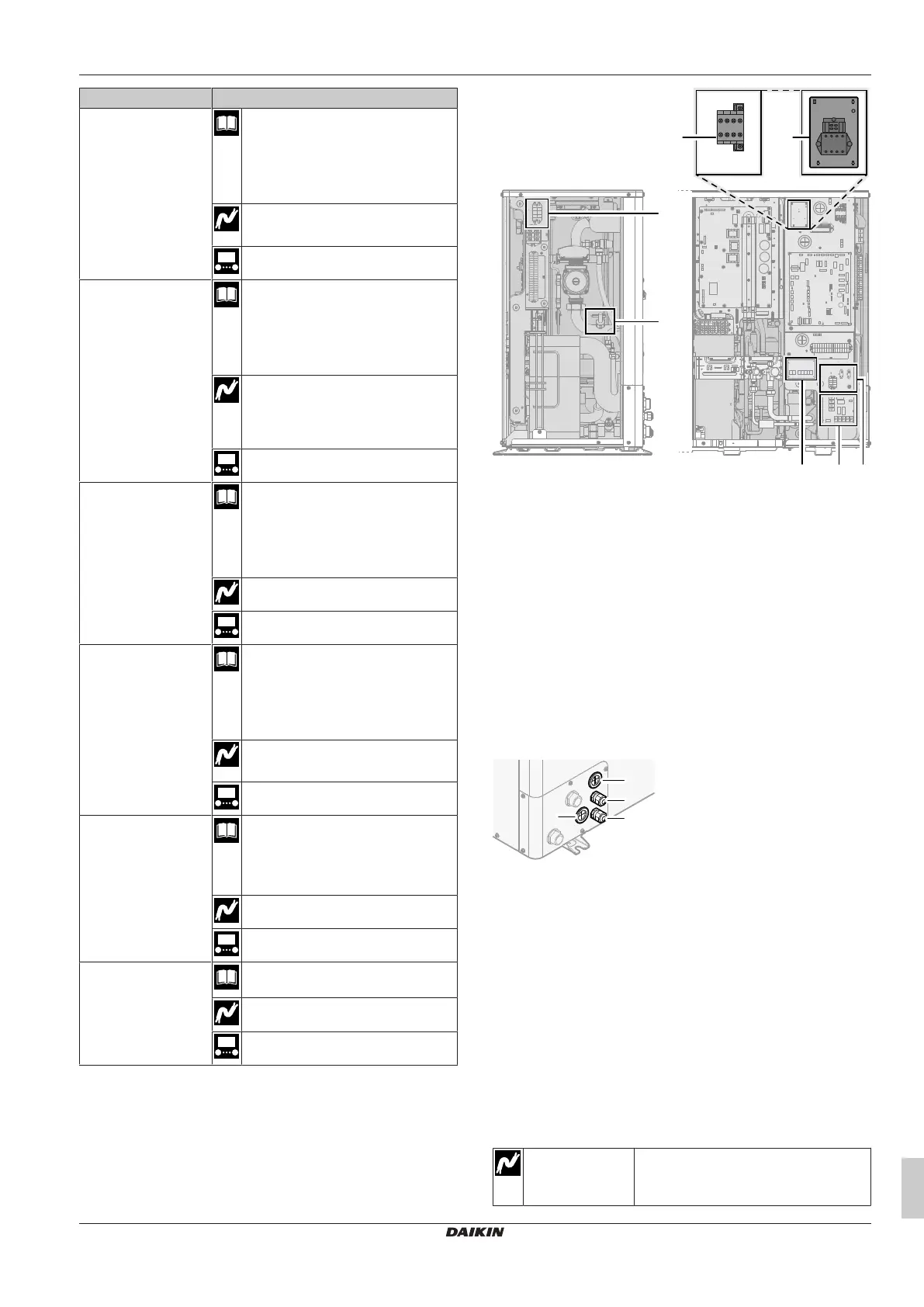
Location extra components
The following illustration shows the location of the extra components
that you need to install on the outdoor unit when using certain option
kits.
a Accessories in standalone domestic hot water tank
(EKHWS*D* and EKHWSU*D*)
a1: Contactor
a2: Terminal block
b Connection kit for third‑party tank with built‑in thermostat
(EKHY3PART2)
c Flow switch (EKFLSW1)
d Demand PCB (A8P: EKRP1AHTA)
e Digital I/O PCB (A4P: EKRP1HBAA)
f Smart grid relay kit (EKRELSG)
6.3.1 To connect the electrical wiring to the
outdoor unit
1 Open the service cover. See "4.3.1 To open the outdoor
unit"[417].
2 Insert the cables at the back of the unit, and route them through
the unit to the appropriate terminal blocks.
a High voltage options
b Low voltage options
c Power supply for backup heater (in case of unit with
integrated backup heater)
Wiring for backup heater kit (in case of external backup
heater kit)
d Unit power supply
3 Connect the wires to the appropriate terminals, and fix the
cables with cable ties.
6.3.2 To connect the main power supply
This topic describes 2 possible ways to connect the main power
supply:
▪ In case of normal kWh rate power supply
▪ In case of preferential kWh rate power supply
In case of normal kWh rate power supply
Normal kWh rate
power supply
Wires: 1N+GND, OR 3N+GND
Maximum running current: Refer to name
plate on unit.