6 Electrical installation
Installation manual
30
EBLA09~16D + EDLA09~16D
Daikin Altherma 3 M
4P620239-1B – 2022.05
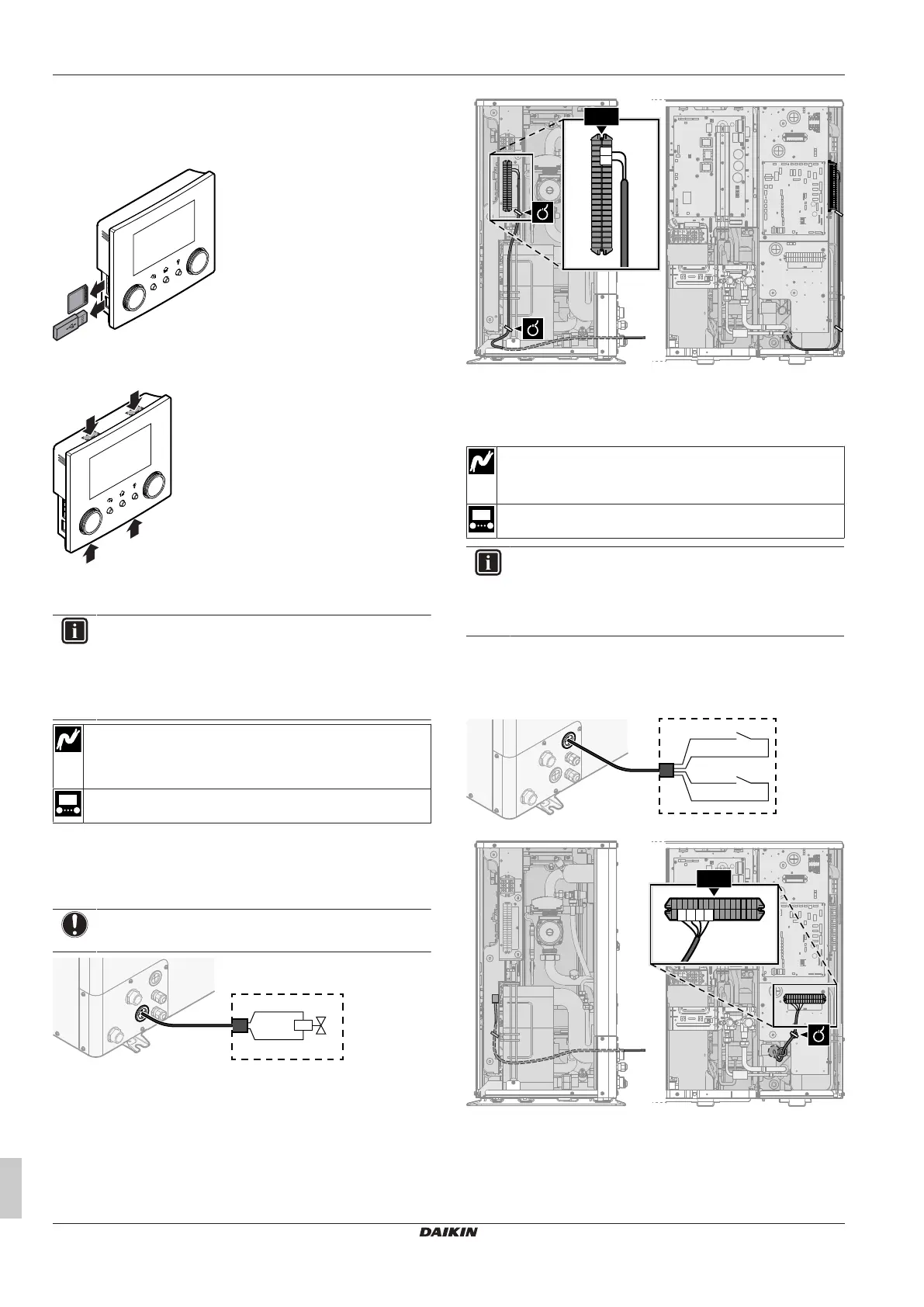
Opening the user interface after it is installed
If you need to open the user interface after it is installed, proceed as
follows:
1 Remove the WLAN cartridge and USB memory stick (if any).
2 Push the rear plate on each of the 4 spots where the snap-fits
are located.
6.3.6 To connect the shut-off valve
INFORMATION
Shut-off valve usage example. In case of one LWT zone,
and a combination of underfloor heating and heat pump
convectors, install a shut-off valve before the underfloor
heating to prevent condensation on the floor during cooling
operation.
Wires: 2×0.75mm²
Maximum running current: 100mA
230VAC supplied by PCB
—
1 Open the service cover. See "4.3.1 To open the outdoor
unit"[417].
2 Connect the valve control cable to the appropriate terminals as
shown in the illustration below.
NOTICE
Only connect NO (normally open) valves.
3 Fix the cable with cable ties to the cable tie mountings.
6.3.7 To connect the electricity meters
Wires: 2 (per meter)×0.75mm²
Electricity meters: 12VDC pulse detection (voltage supplied
by PCB)
[9.A] Energy metering
INFORMATION
In case of an electricity meter with transistor output, check
the polarity. The positive polarity MUST be connected to
X5M/6 and X5M/4; the negative polarity to X5M/5 and
X5M/3.
1 Open the service cover. See "4.3.1 To open the outdoor
unit"[417].
2 Connect the electricity meters cable to the appropriate terminals
as shown in the illustration below.
S2S
X5M.6
X5M.5
X5M.4
X5M.3
S3S
3 Fix the cable with cable ties to the cable tie mountings.