6 Electrical installation
Installation manual
29
EBLA09~16D + EDLA09~16D
Daikin Altherma 3 M
4P620239-1B – 2022.05
[2.9] Control
[1.6] Room sensor offset
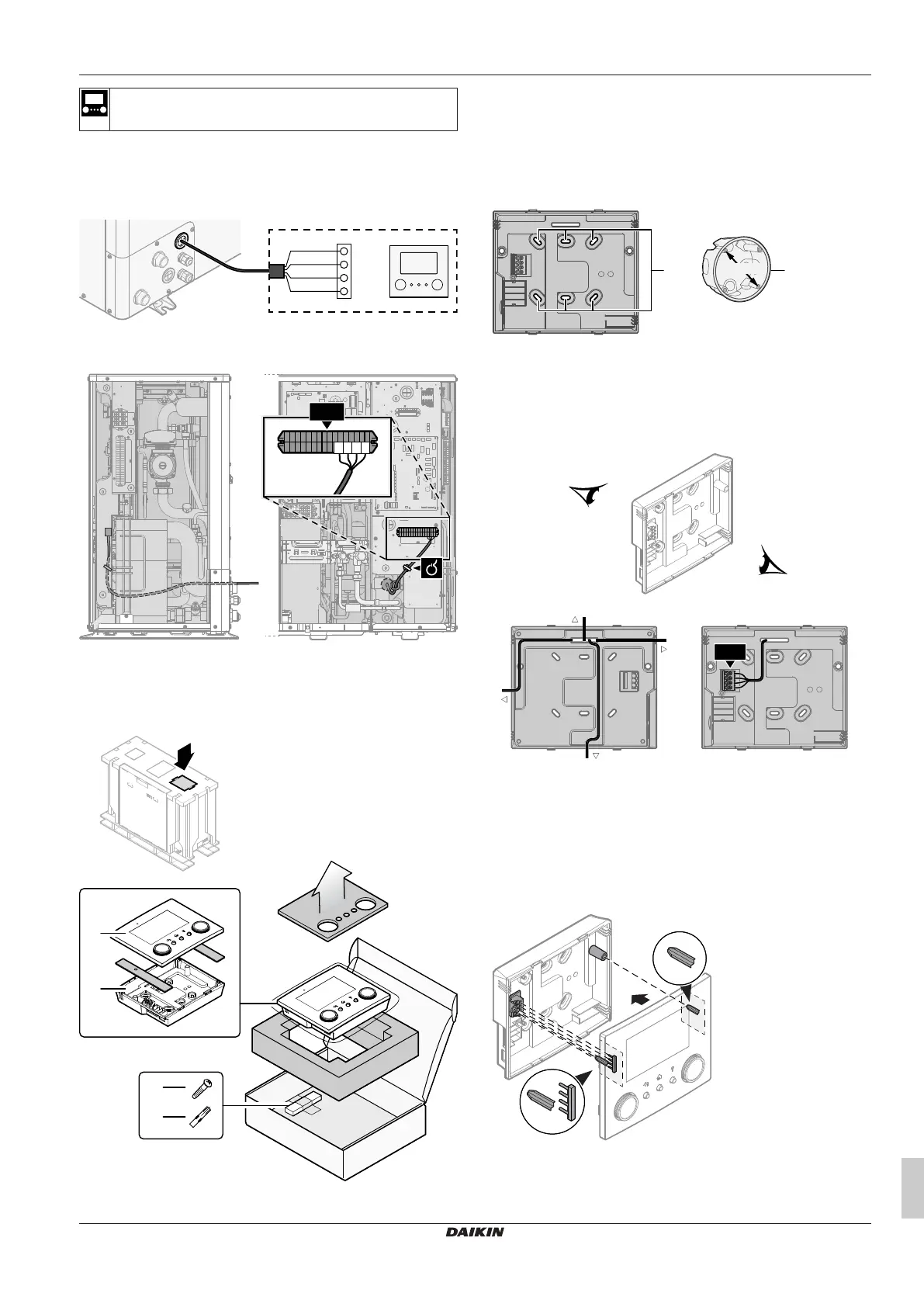
1 Open the service cover. See "4.3.1 To open the outdoor
unit"[417].
2 Connect the user interface cable to the outdoor unit. Fix the
cable with cable ties to the cable tie mountings.
X5M.15
X1B
X5M.16
X5M.11
X5M.12
+12V
−12V
P2
P1
a User interface: Required for operation. Delivered with the
unit as accessory.
Installing the user interface, and connecting the user interface
cable to it
You need the following user interface accessories (delivered on top
of the unit):
a Front plate
b Rear plate
c Screws
d Wall plugs
1 Mount the rear plate to the wall.
▪ Use the 2 screws and wall plugs.
▪ Use any of the 6 holes. The holes are compatible with
standard electrical box extenders of 60mm.
a Holes
b Electrical box extender (field supply)
2 Connect the user interface cable to the user interface.
▪ Choose one of the 4 possible wiring intakes (a, b, c or d).
▪ If you choose the left or right side, make a hole for the cable
in the part of the casing where the casing is thinner.
a Top side
b Left side
c Bottom side
d Right side
3 Mount the front plate.
▪ Align the positioning pins and push the front plate onto the
rear plate until it moves into place with a click.
▪ The connector pins are automatically inserted correctly.
a Positioning pins
b Connector pins