6 Electrical installation
Installation manual
32
EBLA09~16D + EDLA09~16D
Daikin Altherma 3 M
4P620239-1B – 2022.05
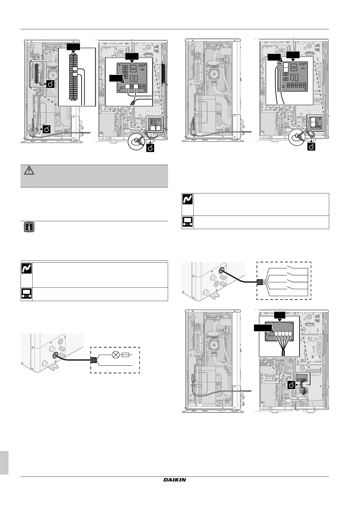
a Installation of EKRP1HBAA is required.
WARNING
Stripped wire. Make sure that stripped wire cannot make
contact with possible water on the bottom plate.
3 Fix the cable with cable ties to the cable tie mountings.
6.3.11 To connect the changeover to external
heat source
INFORMATION
Bivalent is only possible in case of 1 leaving water
temperature zone with:
▪ room thermostat control, OR
▪ external room thermostat control.
Wires: 2×0.75mm²
Maximum load: 0.3A, 250VAC
Minimum load: 20mA, 5VDC
[9.C] Bivalent
1 Open the service cover. See "4.3.1 To open the outdoor
unit"[417].
2 Connect the changeover to external heat source cable to the
appropriate terminals as shown in the illustration below.
a Installation of EKRP1HBAA is required.
3 Fix the cable with cable ties to the cable tie mountings.
6.3.12 To connect the power consumption digital
inputs
Wires: 2 (per input signal)×0.75mm²
Power limitation digital inputs: 12VDC / 12mA detection
(voltage supplied by PCB)
[9.9] Power consumption control.
1 Open the service cover. See "4.3.1 To open the outdoor
unit"[417].
2 Connect the power consumption digital inputs cable to the
appropriate terminals as shown in the illustration below.
S6S (DI4)
A8P.1
A8P.2
A8P.3
A8P.4
A8P.5
S7S (DI3)
S8S (DI2)
S9S (DI1)
a Installation of EKRP1AHTA is required.
3 Fix the cable with cable ties to the cable tie mountings.