6 Electrical installation
Installation manual
33
EBLA09~16D + EDLA09~16D
Daikin Altherma 3 M
4P620239-1B – 2022.05
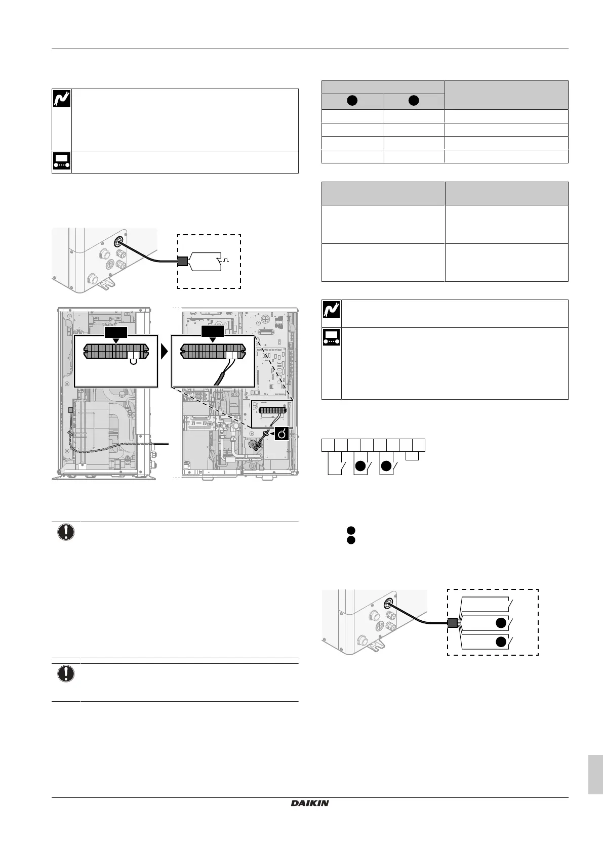
6.3.13 To connect the safety thermostat
(normally closed contact)
Wires: 2×0.75mm²
Maximum length: 50m
Safety thermostat contact: 16VDC detection (voltage
supplied by PCB). The voltage-free contact shall ensure the
minimum applicable load of 15VDC, 10mA.
—
1 Open the service cover. See "4.3.1 To open the outdoor
unit"[417].
2 Connect the safety thermostat (normally closed) cable to the
appropriate terminals as shown in the illustration below.
a Remove jumper
3 Fix the cable with cable ties to the cable tie mountings.
NOTICE
Make sure to select and install the safety thermostat
according to the applicable legislation.
In any case, to prevent unnecessary tripping of the safety
thermostat, we recommend the following:
▪ The safety thermostat is automatically resettable.
▪ The safety thermostat has a maximum temperature
variation rate of 2°C/min.
▪ There is a minimum distance of 2m between the safety
thermostat and the motorized 3‑way valve delivered
with the domestic hot water tank.
NOTICE
Error. If you remove the jumper (open circuit) but do NOT
connect the safety thermostat, stop error 8H-03 will occur.
6.3.14 To connect a Smart Grid
This topic describes 2 possible ways to connect the outdoor unit to a
Smart Grid:
▪ In case of low voltage Smart Grid contacts
▪ In case of high voltage Smart Grid contacts. This requires the
installation of the Smart Grid relay kit (EKRELSG).
The 2 incoming Smart Grid contacts can activate the following Smart
Grid modes:
Smart Grid contact Smart Grid operation mode
0 0 Free running
0 1 Forced off
1 0 Recommended on
1 1 Forced on
The use of a Smart Grid pulse meter is not mandatory:
If Smart Grid pulse meter is… Then [9.8.8] Limit setting kW
is…
Used
([9.A.2] Electricity meter 2 ≠
None)
Not applicable
Not used
([9.A.2] Electricity meter 2 =
None)
Applicable
In case of low voltage Smart Grid contacts
Wires (Smart Grid pulse meter): 0.5mm²
Wires (low voltage Smart Grid contacts): 0.5mm²
[9.8.4]=3 (Benefit kWh power supply = Smart grid)
[9.8.5] Smart grid operation mode
[9.8.6] Allow electrical heaters
[9.8.7] Enable room buffering
[9.8.8] Limit setting kW
The wiring of the Smart Grid in case of low voltage contacts is as
follows:
1413
S11S
65
S4S
43
X5M
S10S
109
a
2 1
a Jumper (factory-mounted). If you also connect a safety
thermostat (Q4L), replace the jumper with the safety
thermostat wires.
S4S Smart Grid pulse meter (optional)
/S10S
Low voltage Smart Grid contact 1
/S11S
Low voltage Smart Grid contact 2
1 Open the service cover. See "4.3.1 To open the outdoor
unit"[417].
2 Connect the wiring as follows:
X5M.4
X5M.3
S4S
X5M.10
X5M.9
S10S
X5M.6
X5M.5
S11S
1
2