13
15.1 Auxiliary Alarm Switch
The control is equipped with two Auxiliary Alarm termi-
nals, labeled TB4 and TB5 which are typically utilized in
series with a condensate switch but could also be used
with compatible CO
2
sensors or re alarms.
The auxiliary alarm switch must be normally closed and
open when the alarm occurs. For example, a normally
closed condensate switch will open when the base pan’s
water level reaches a particular level. The control will
respond by turning off the blower motor and outdoor unit
and displaying the proper fault codes. If the switch is
later detected closed for 30 seconds, normal operation
resumes and the error message is removed. (The switch
is closed as part of the default factory setting.) The error
will be maintained in the equipment’s fault history. See
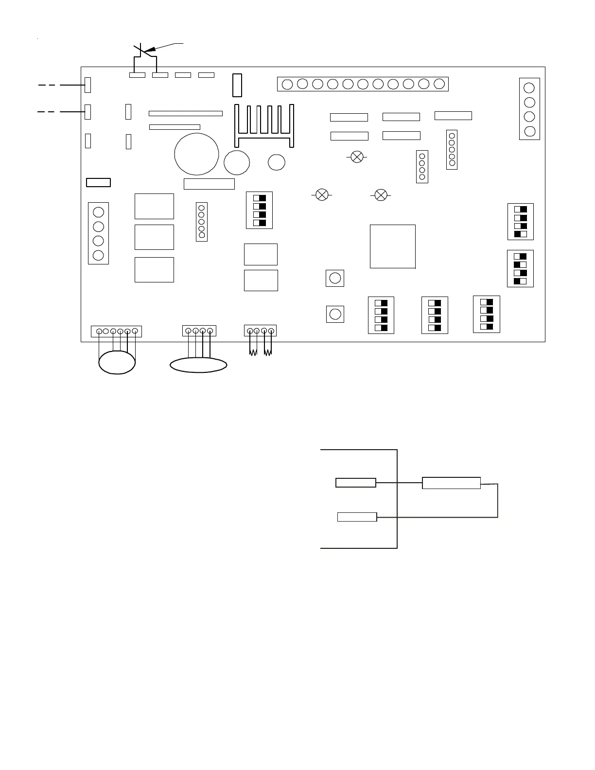
Figures 15 and 16 for the connection location.
Figure 16
. INDOOR UNIT COMMUNICATING BOARD (PCB)
Figure 15
X3A
X15A
X5A
SEG2
SEG1
X12A
X13A
X8A
THERMISTOR
Micro
Processor
PRESSURE SENSOR
EEV
COIL
FUSE
TB4
TB1
TB5
TB2
C
R
2
1
S1 S2 S3 S4
Heater Kit
Output
ECM Motor
ON
OFF
DS1
DS2
DS3
D
S
4
D
S
5
F
US
E
F
1
U
X
1
A
SHARE DATA
S5 S6 S7 S8
S9 S10 S11 S12
S13 S14 S15 S16
S17 S18 S19 S20
S21 S22
F
2
U
T
B
6
T
B
8
T
B
7
T
B
1
0
T
B
3
D
S
6
O
N
O
F
F
7seg
7seg
X
2
A
X
7
A
C
R
2
1
AUXALARM
C
R
2
1
ACC-OUT
ACC-IN
(Accessory)
(Accessory)
B
S
2
B
S
1
F
A
U
L
T
R
E C
A
L L
LE
A
R
N
RX LED
CPU LED
STA TUS LE D

 Loading...