4
6 INSTALLATION LOCATION
NOTE: These air handlers are designed for indoor
installation only.
If the unit is located in an unconditioned area with high
ambient temperature and/or high humidity, the air handler
may be subject to nuisance sweating of the casing. On these
installations, a wrap of 2” berglass insulation with a vapor
barrier is recommended.
The EEV Series Air Handler product line may be installed in
one of the upow, downow, horizontal left or horizontal right
orientations as shown in Figures 3, 4, 5 and 6. The unit may
be installed in upow or horizontal left orientation as shipped
(refer to specic sections for more information).
Minor eld modications are necessary to convert to downow
or horizontal right as indicated in below sections.
For DV*FEC installations in areas where the return air envi-
roment sees humidity levels above 65% relative humidity, a
High Humidity Kit (HHK) must be used. See Table 1 for Model
and Kit assignment.
6.1 Upow Installation
No eld modications are mandatory however to obtain
maximum efciency, the horizontal drip shield, side drain
pan and drain pan extension, can be removed.
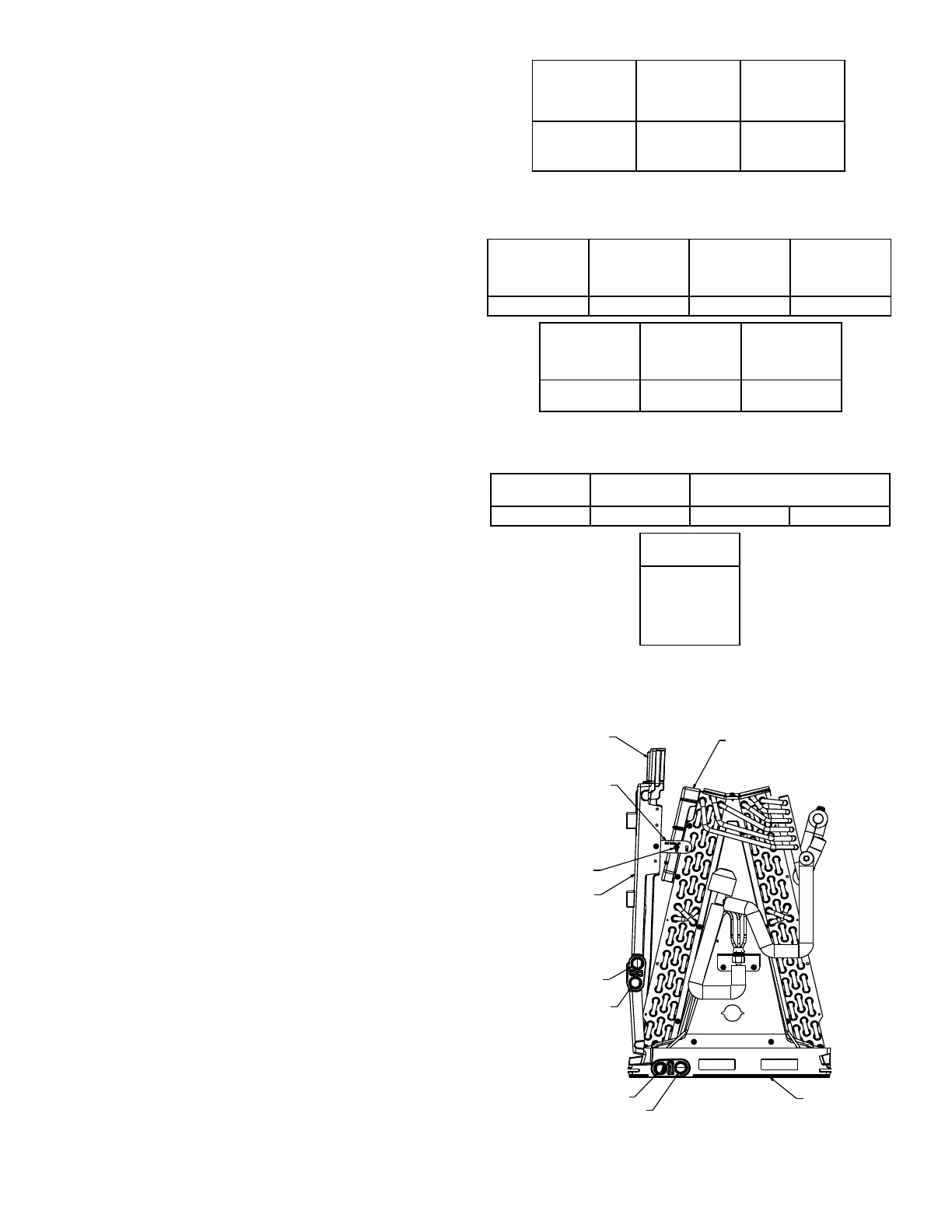
Side Drain Pan and Extension Removal: Refer to Figure
1, remove the two (2) screws that secure the drip shield
support brackets to the condensate collectors (front and
back). Unsnap the side drain pan from the bottom drain
pan using a screw driver or any small lever. The side drain
pan, drip shield brackets and the drain pan extension may
now be removed. From Figure 1, drain port labeled (A)
is the primary drain for this application and condensate
drain line must be attached to this drain port. Drain port
(a) is for the secondary drain line (if used).
6.2 Horizontal Left Installation
No eld modications are permissible for this application.
Drain port labeled (B) in Figure 1 is the primary drain
for this application and condensate drain line must be
attached to this drain port. Drain port (b) is for the sec-
ondary drain line (if used).
In applications where the air handler is installed in the
horizontal left or right position, and the return air envi-
ronment see humidity levels above 65% relative humidity
coupled with total external static levels above 0.5” e.s.p., a
Condensate Management Kit (CMK) is available for eld
application. Kit nomenclature can be found in the table 2.
6.3 Downow/Horizontal Right Installation
IMPORTANT NOTE: In the downow application, to
prevent coil pan “sweating”, the mandatory downow
kit (DFK) is available through your local Daikin distrib-
utor. The DFK is not supplied with the air handler and
is required to minimize pan sweating on all downow
installations. See Table 3 for the correct DFK and follow
the instructions provided for installation.
HIGH HUMIDITY KIT
Table 1
HHK0001
High
Humidity Kit
HHK0002
High
Humidity Kit
HHK0003
High
Humidity Kit
DV24FECB14 DV36FECC14
DV42FECC14
DV48FECD14
DV60FECD14
CONDENSATE KIT
Table2
CMK0008
Condensate
Kit
CMK0009
Condensate
Kit
CMK0010
Condensate
Kit
CMK0011
Condensate
Kit
DV25P ECB14 DV37PECC14 DV59PECD14 DV61P ECD14
CMK0012
Condensate
Kit
CMK0013
Condensate
Kit
CMK0014
Condensate
Kit
DV24FECB14 DV36FECC14
DV42FECC14
DV48FECD14
DV60FECD14
DOWNFLOW KIT
Table3
DFK-B
Downflow Kit
DFK-C
Downflow Kit
DFK-D
Downflow Kit
DV25P ECB14 DV37P ECC14 DV59P ECD14 DV61P ECD14
DFKE-02
DV24FECB14
DV36FECC14
DV42FECC14
DV48FECD14
DV60FECD14
Downflow Kit
DRIP SHIELD REMOVAL
Figure 1
Screw
Extension
Horizontal
Drip Shield
b
Side Drain Pan
A
B
a
Drip Shield
Bracket
Bottom
Drain Pan

 Loading...