17
SYSTEM WIRING
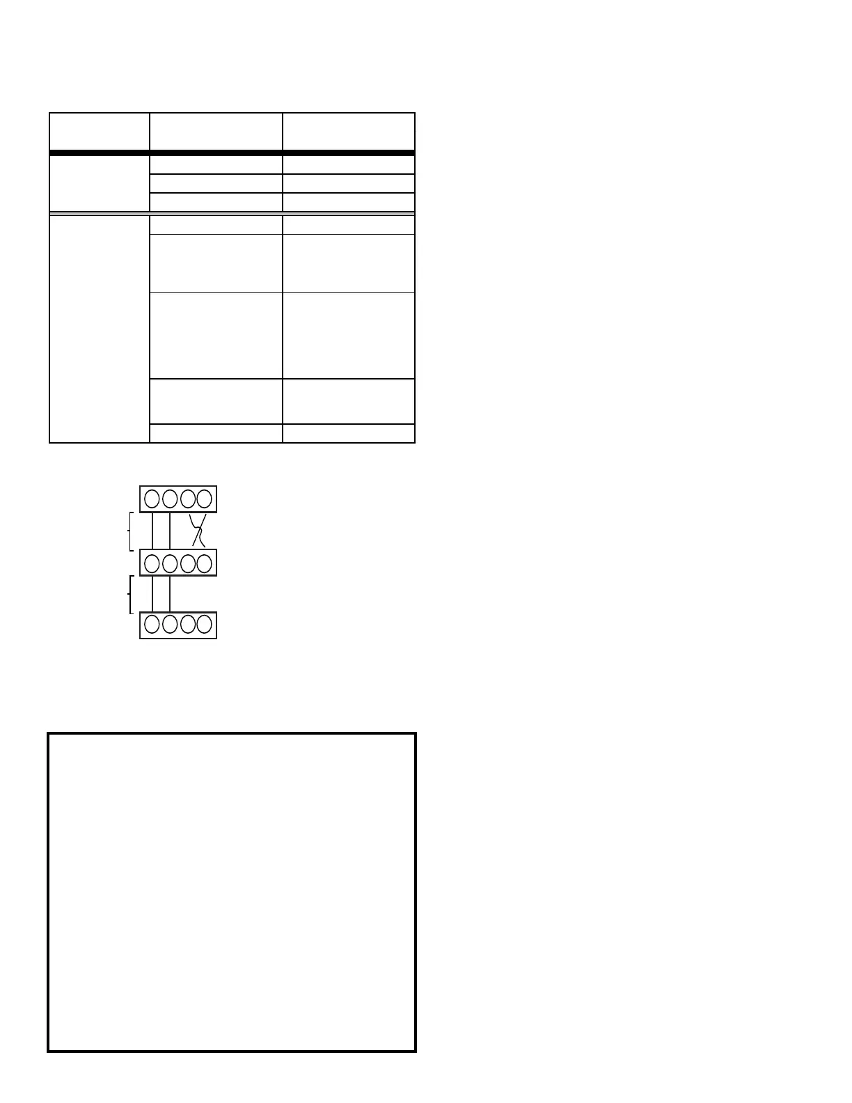
Figure 20
1 2 C R
1 2 R C
1 2 R C
Communicang Thermostat
125 .(*)
Air Handler Blower Integrated
Control Module
250 .(*)
Heat Pump Integrated
Control Module
(*) Allowable Maximum Length
1 2 C R
1 2 R C
1 2 R C
Communicang Thermostat
125 .(*)
Air Handler Blower Integrated
Control Module
250 .(*)
Heat Pump Integrated
Control Module
(*) Allowable Maximum Length
Cooling Air Conditioner
Heating Air Handler
Continuous Fan Thermostat
Cooling Heat Pump
Greater than of Heat
Pump of Air Handler
Demand
Electric Heat Strips
Only
Continuous Fan Thermostat
Air Conditioner +
Air Handler
ATTENTION INSTALLER -
IMPORTANT NOTICE!
Please read carefully before installing this unit.
• Power line terminal #C from Indoor unit must connect
to terminal #C on thermostat and power line terminal
#R from indoor unit must connect to terminal #R on
thermostat. Verify wires are not reversed. (Note:The
order of the terminals of the indoor unit and the Daikin
One+ thermostat may be different.)
• Do not attach any wires to the R & C Terminals on the
AC/HP, as they are not needed for inverter unit.
• Data line terminal #1 from AC/HP must connect to
terminal #1 on indoor unit and thermostat and data
line terminal #2 from AC/HP must connect to terminal
#2 on indoor unit and thermostat. Verify wires are not
reversed.
17.5 System Troubleshooting
NOTE: Refer to the instructions accompanying the
Communicating compatible outdoor AC/HP unit for
unit specic troubleshooting information. Refer to the
Troubleshooting Chart at the end of this manual for
a listing of possible air handler error codes, possible
causes and corrective actions.
Table 11

 Loading...