9 | Electrical installation
Installer reference guide
97
ERLA03DAV3 + EHFZ03S18DJ3V
Daikin Altherma 3 R F
4P596821-1B – 2021.10
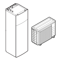
a Factory-mounted cable connected to the contactor of the backup heater, inside the
switch box (K1M)
b Field wiring (see table below)
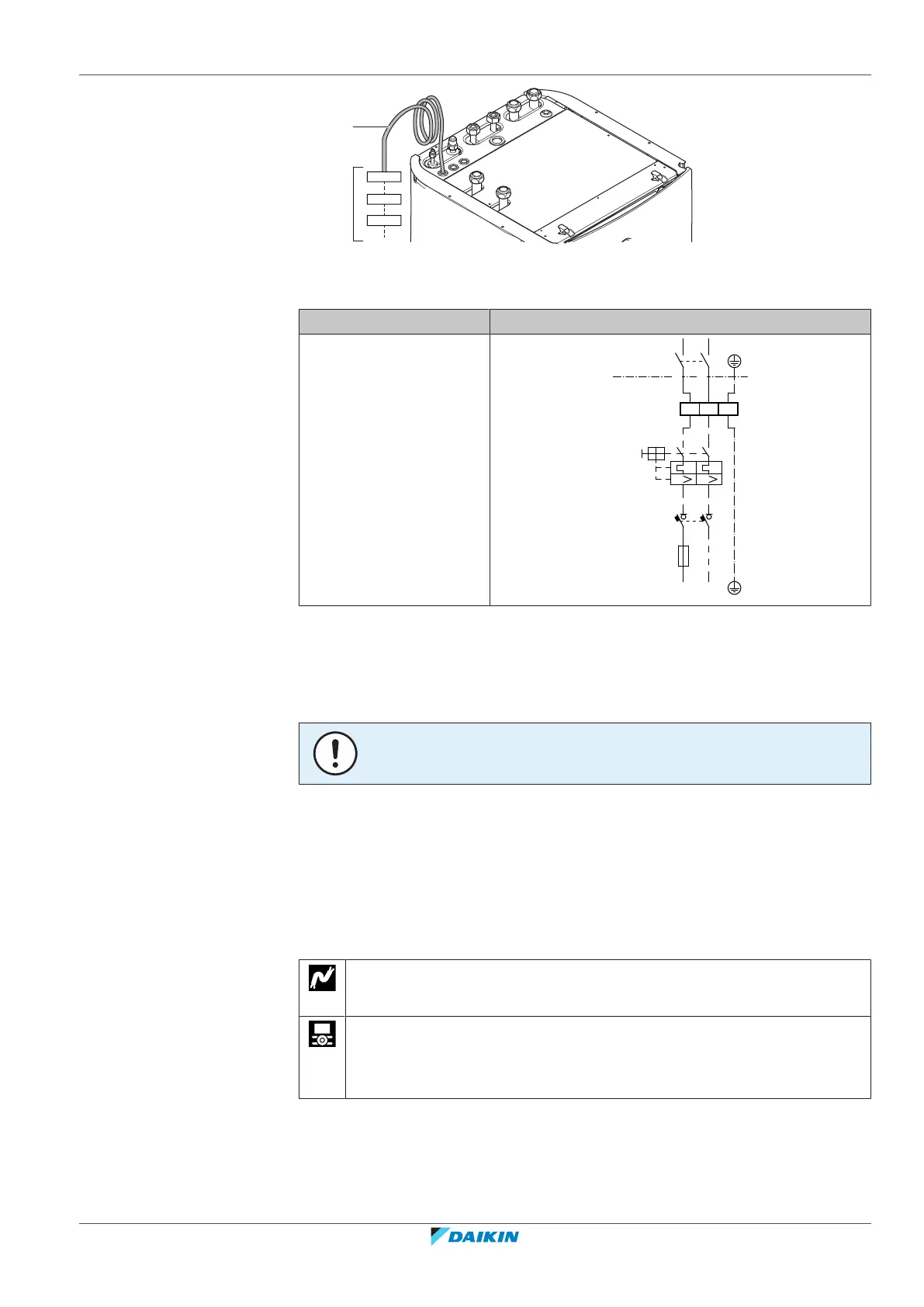
Model (power supply) Connections to backup heater power supply
*3V (1N~230V)
F1B Overcurrent fuse (field supply). Recommended fuse: 2‑pole; 16A; curve 400V;
tripping class C.
K1M Contactor (in the lower switch box)
Q1DI Earth leakage circuit breaker (field supply)
SWB Switch box
X6M Terminal (field supply)
NOTICE
Do NOT cut or remove the backup heater power supply cable.
9.3.3 To connect the user interface
▪ If you use 1 user interface, you can install it at the indoor unit (for control close
to the indoor unit), or in the room (when used as room thermostat).
▪ If you use 2 user interfaces, you can install 1 user interface at the indoor unit (for
control close to the indoor unit) + 1 user interface in the room (used as room
thermostat).
Wires: 2 (per user interface)×(0.75~1.25mm²)
Maximum length: 200m
[A.2.1.7] Unit control method
[A.2.1.B] User interface location
[A.3.2.2] Room temp. offset
1 Open the following (see "7.2.4To open the indoor unit"[455]):