17 | Technical data
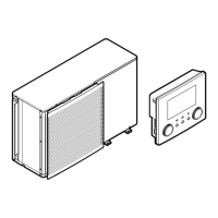
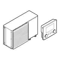
Installer reference guide
218
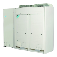
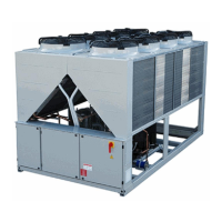
EWAA011~016DA + EWYA009~016DA
Packaged air-cooled water chillers
and packaged air to water heat pumps
4P620242-1 – 2020.06
17.2 Piping diagram: Outdoor unit
3D128954A
R4T
R1T
R3T
R5T
R4T
R1T
R3T
R2T
M1C
S1PH
S1PL
S1NPH
Y1E
Y3E
Y1S
a
c
d
f
j
i
g
h
l
k
s
q
o
r
m
n
p
u
u
e
m
t
b
*
**
B1PW
1N~
*
1N~
**
3N~
**
3N~
*
A B
A Hydro module B1PW Space heating water pressure sensor
B Compressor module M1C Compressor
S1PH High pressure switch
a Water IN (screw connection, male, 1") S1PL Low pressure switch
b Water OUT (screw connection, male, 1") S1NPH Pressure sensor
c Drain valve (water circuit) Y1E Electronic expansion valve (main)
d Plate heat exchanger Y3E Electronic expansion valve (injection)
e Flow sensor Y1S Solenoid valve (4-way valve)
f Expansion vessel
g Safety valve Thermistors (hydro module):
h Manual air purge valve R1T Outlet water heat exchanger
i Pump R3T Refrigerant liquid side
j Connection for optional flow switch R4T Inlet water
k Liquid stop valve with service port
l Gas stop valve with service port Thermistors (compressor module):
m Filter R1T Outdoor air
n Rectifier R2T Compressor discharge
o Economiser R3T Compressor suction
p Heat sink R4T Air heat exchanger
q Distributor R5T Air heat exchanger, middle
r Heat exchanger
s Service port 5/16" flare Refrigerant flow:
t Accumulator Heating
u Muffler Cooling
Connections:
Screw connection
Flare connection
Quick coupling
Brazed connection
 Loading...