9 | Electrical installation
Installer reference guide
87
EWAA011~016DA + EWYA009~016DA
Packaged air-cooled water chillers
and packaged air to water heat pumps
4P620242-1 – 2020.06
3kW
1N~ 230V
6kW
1N~ 230V
6kW
3N~ 400V
9kW
3N~ 400V
K2M/1 K5M/13 ∞ 26.5Ω ∞ ∞
K2M/3 ∞ ∞ 52.9Ω 52.9Ω
K2M/5 ∞ ∞ 52.9Ω 52.9Ω
K2M/3 K2M/5 52.9Ω 52.9Ω 52.9Ω 52.9Ω
K1M/5 K2M/1 ∞ 132.3Ω ∞ ∞
Example measure resistance between K1M/1 and K5M/13:
K1M K2MK2M
1 3 5 13
2 4 6 14
K5M
1 3 5 13
2 4 6 14
1 3 5 13
2 4 6 14
Ω
Ω
To connect the backup heater kit to the outdoor unit
The wiring between the backup heater kit and the outdoor unit is as follows:
1 2 3 4 5
6 7 8 9 10
X3M
X15M
1 2
1 2
X5M
X15M
EKLBUHCB6W
A
B
HV LV
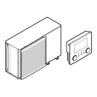
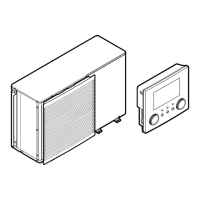
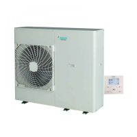
A Outdoor unit
B Backup heater kit
HV High voltage connections (backup heater thermal protector + backup heater
connection)
LV Low voltage connection (backup heater thermistor)
NOTICE
The distance between the high voltage and low voltage cables should be at least
50mm.
1 On the backup heater kit, connect the LV and HV cables to the appropriate
terminals as shown in the illustration below.
 Loading...
