Removal of PCBs Si041048
18 Removal Procedure
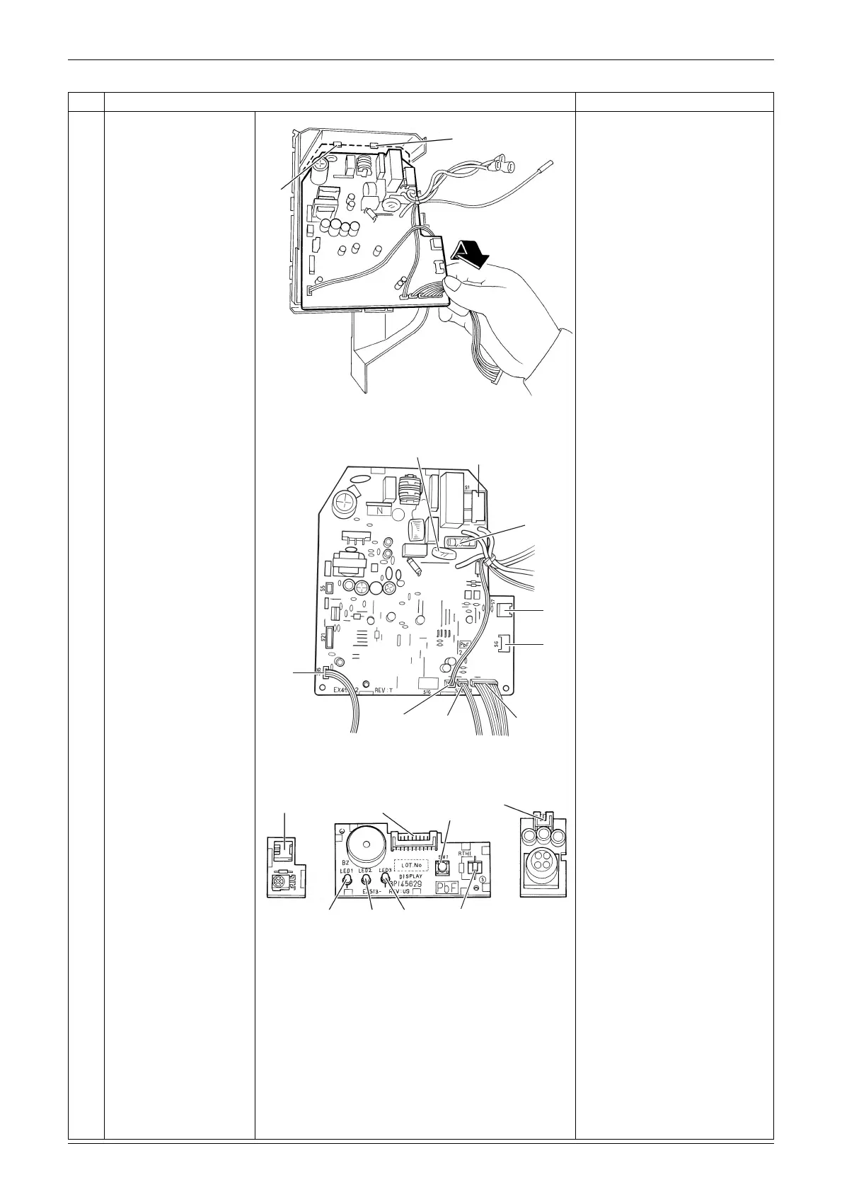
2
Lift up the bottom of the
control PCB and pull it
out.
When reassembling the
control PCB, make sure that
it is fixed by 2 upper hooks.
3
The figures show the
names of the PCB
component parts.
[S1]: fan motor
[S6]: swing motor
[S7]: fan motor (Hall IC)
[S26]: display PCB
[S27]: control PCB
[S28]: signal receiver PCB
[S29]: control PCB
[S32]: indoor heat exchanger
thermistor
[S35]: INTELLIGENT EYE
sensor PCB
[S36]: control PCB
Some models have no
harness for [S7], [S35].
Step Procedure Points
Hook
Hook
(R4370)
[S35]
[S32]
[S6]
Varistor
Fuse
[S1]
(R16422)
[S7]
[S28]
[S26]
[S29]
[S27]
[S36]
SW1
LED 1
(Green)
LED 2
(Yellow)
LED 3
(Green)
Room temperature
thermistor
(R17650)
 Loading...