4 www.daikincomfort.com IO-DPV
Installaon
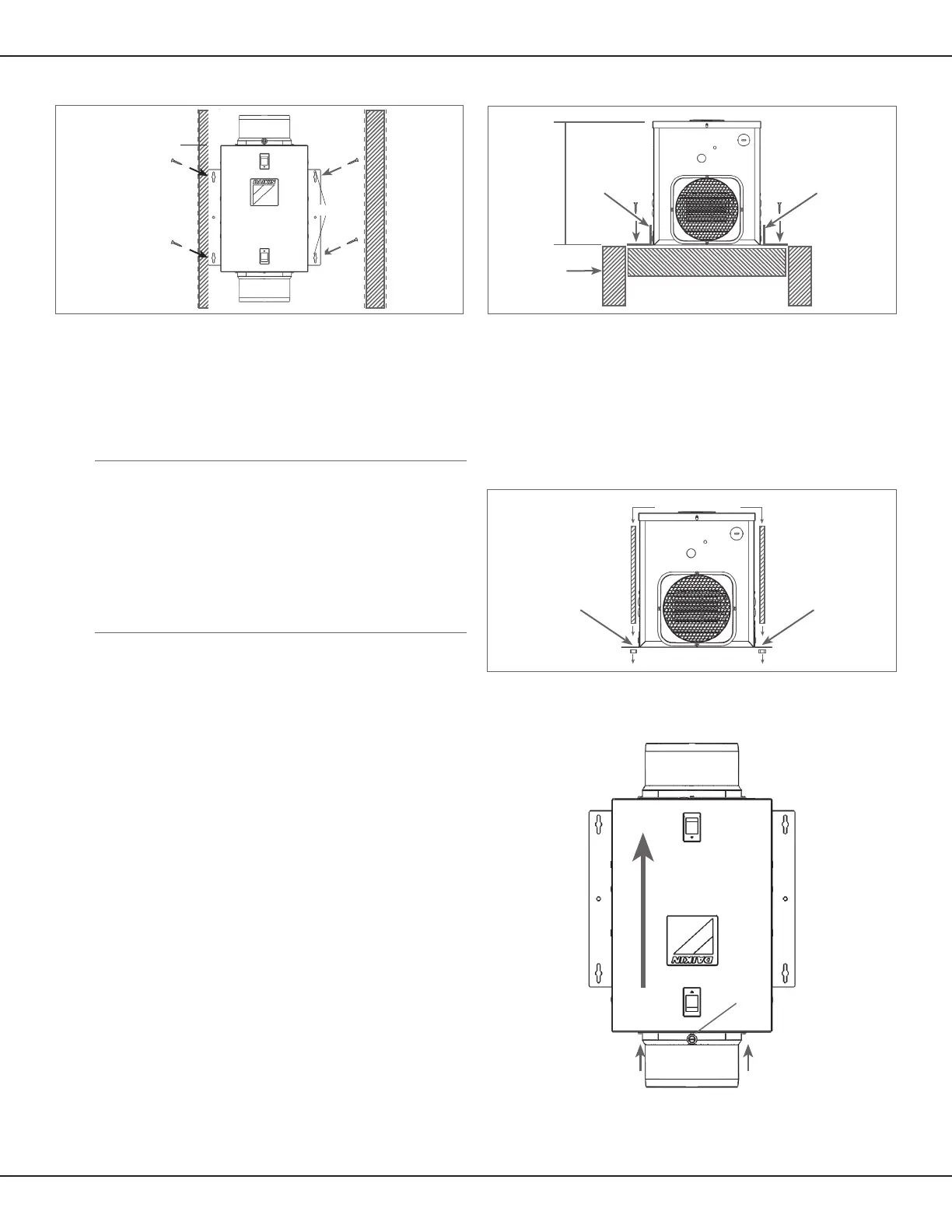
Screws
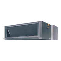
Air Flow
Figure 2 - Mounng venlator to a joist
Joist
2 x 4 Header
Bracket
BracketBracket
Bracket
11½"
Ducng the Venlator
NOTE: 6" diameter or larger rigid duct is recommended for
best performance.
CAUTION!
All ducng must comply with local and naonal building codes.
CAUTION!
The ducng from this venlator to the outside of the building
has a signicant eect on the airow, noise and energy
consumpon of the venlator. Use the shortest, straightest
duct roung possible between the venlator and the home’s
exterior for best performance, and avoid installing the
venlator with smaller diameter ducts than recommended.
Insulaon around the ducts can reduce energy loss and help
inhibit mold growth. Venlators installed with exisng ducts
may not achieve their rated airow.
CAUTION
Make sure the outdoor air intake port complies with all local
and naonal codes and is located at least 6 feet away from
sources of contaminaon such as but not limited to: clothes
dryer exhaust, furnace or central vacuum exhausts, gas appli-
ances such as BBQ grills, garbage bins or other exhaust ports.
Note: To ensure quiet operaon of this venlator, the
ducng
shall be installed using sound aenuaon techniques
appropriate for the installaon. For bathroom and general
venlaon applicaons, at least 8 feet of insulated exible
duct shall be installed between the exhaust or supply grille(s)
and the venlator.
1. Connect ducng to the venlator’s intake and outlet duct
collars (Figure 4), sealing the joints with appropriately
rated tape. Use screws or suitable clamps to secure in
place. Make sure the outdoor air intake is connected to
an intake port ed with a suitable Air Intake Hood with
insect screen to protect air intake. It is recommended that
low restricon terminaon ngs be used.
2. To reduce the potenal for condensaon buildup within
the duct, seal duct joints and exterior penetraons with
masc, caulk or other appropriate material to create an
air-ght path to and from the venlator.
3. To reduce the potenal for building heat loss or gain and to
reduce the potenal for condensaon, wrap insulaon
around duct and/or venlator.
i
i
i
NOTE: At the base of the intake duct collar, there is a small test port
hole covered with a red plasc cap. Make sure the test port is not
covered up by the ducng or insulaon and can be accessed for
owrate measurement. To access the port, remove the red, plasc
port cover and insert pitot tube to measure owrate.
Figure 3 - Mounng venlator using hanging rods
Housing
Threaded Rod
Figure 4 - Connecng ducng to the venlator
Figure 1 - Surface mounng of venlator
Intake
Ducng
Test Port
Outlet
Ducng
Air Flow
Stud/Joist
Anchors