IO-DPV www.daikincomfort.com 5
Installaon
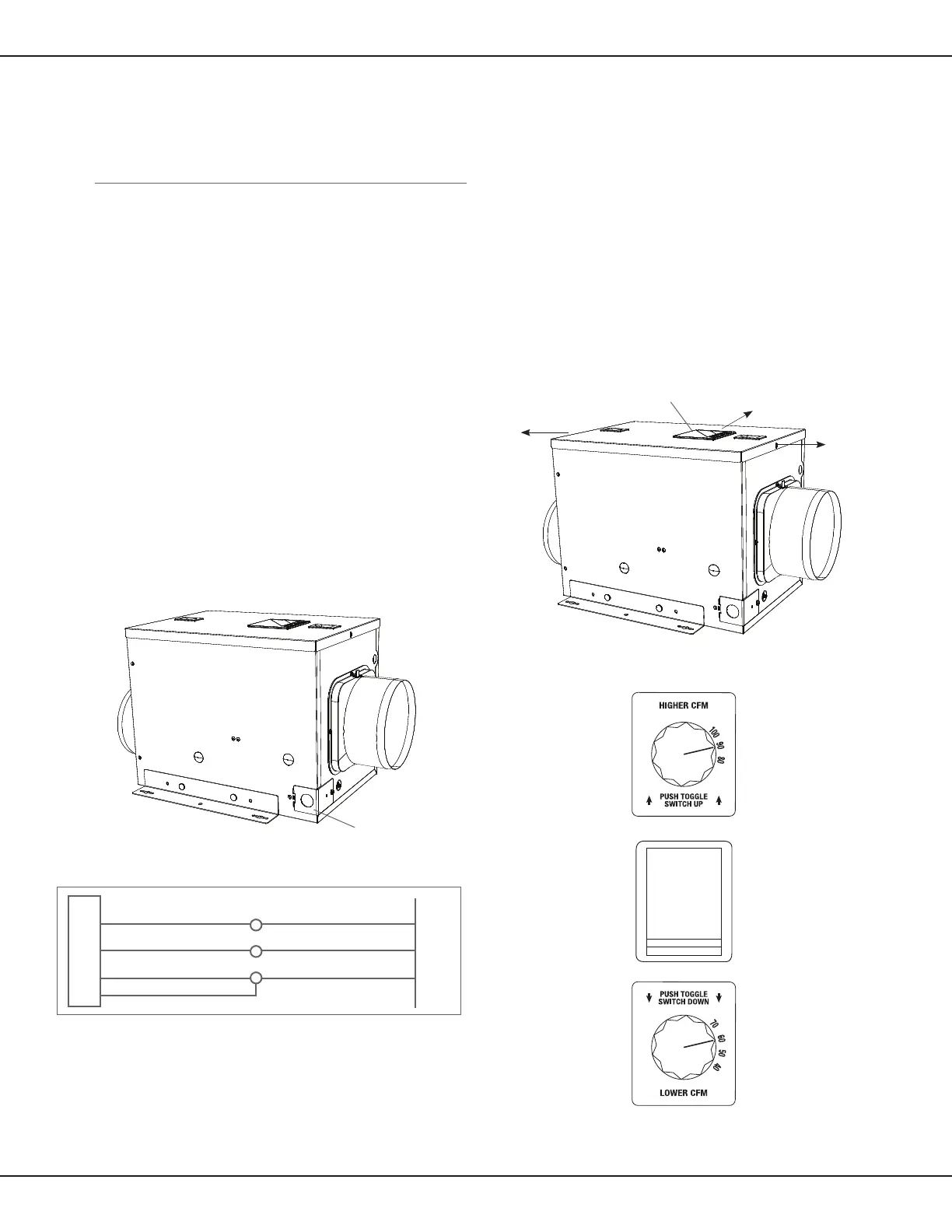
Figure 5 - Remove the wire compartment cover
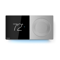
Figure 7 - Control Compartment Cover
i
i
Wiring the Venlator
CAUTION!
Make sure power is switched o at service panel before
starng electrical work.
CAUTION!
Installaon work and electrical wiring must be done by
qualied person(s) in accordance with all applicable codes and
standards, including re-related construcon.
Note: This unit includes a small, wiring compartment for
making electrical connecons to the main power
1. Remove the wire compartment cover screw and set
aside the screw and cover in a secure place (Figure 5).
2. Pull the loose black, white and green wires out from the wire
compartment (addional wires will be present).
Install an approved
cable connector to the hole in the wire
compartment cover (not included) to protect the wire from
being cut by the sharp metal of the hole in the cover. Run a black
(hot), white (neutral), and a green or bare ground wire from the
supply through the cable connector. Connect all wires
from the supply to their corresponding wires within the
wire compartment (Figure 6). Use approved methods for
all connecons.
3. Carefully tuck wires back inside the wire compartment
and replace wire compartment cover securing it with the
screw that was removed earlier.
Seng the Venlaon Flowrate
1. Determine the CFM desired for venlang the home. This unit
can be set to deliver between 40 CFM and 100 CFM of outdoor
air to the home in increments of 10 CFM.
2. Remove the screws securing the control compartment cover
(a) and remove the cover (b) to gain access (Figure 7).
Locate the speed control panel inside the unit.
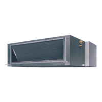
3. Flowrate Selecon
a. For owrate of 40 CFM to 70 CFM: Push the toggle switch
DOWN towards the “LOWER CFM” speed dial, then set the
speed dial to the desired CFM (Figure 8).
b. For sengs of 80 CFM to 100 CFM: Push the toggle switch
UP towards the “HIGHER CFM” speed dial, then set the speed
dial to the desired CFM (Figure 8).
Figure 6
Supply from house
Black
Neutral (White)
Ground (Green or Bare)
Venlator Wiring
Compartment
Neutral (White)
Green
Black
Green
Figure 8 - Speed Control Panel
Wire Compartment Cover
a) Remove screws
b) Remove cover
a) Remove screws
Wire Compartment Cover