6 www.daikincomfort.com IO-DPV
Installaon
Inline Media Air Filter
This venlator includes a high eciency MERV 16 inline media air
lter which helps remove airborne parculates from the intake air.
This lter has nominal dimensions of 10” x 10” x 2” with actual
dimensions of 9.5” x 9.5” x 1-11/16”.
NOTE: Inserng this lter in the airow path decreases the airow
delivered by the unit. And owrate is further decreased as the lter
traps parcles from the incoming air. As a result, the lter must
be changed periodically to avoid excessive reducon in owrate.
In certain installaons, the MERV 16 lter may be found to be
too restricve, reducing the airow too much. In those cases, a
replacement MERV 13 lter – part number DQ-P-F-13 should
be considered.
Installing or Changing the Air Filter:
1. Remove the two screws securing the control compartment
cover and remove the cover to gain access to the controls and
lter area (Figure 7).
2. Pull out the exhausted lter from the Control Compartment and
place in the garbage.
3. Insert a new lter into the slot in the housing where the ex-
hausted lter was installed. Make sure the lter is seated all the
way to the boom of the housing (Figure 9).
4. Close the control compartment cover and reinstall the screws
holding it in place.
Conguring the Controller
The controller mounted inside the venlator monitors the
temperature and humidity of the incoming air. The installer of
this venlator can congure this controller to suit the venlaon
requirements of the home. Before conguring the controller,
remove the protecve plasc lm from the controller’s LCD screen.
With power to the venlator turned on, the inial screen will
show OFF. Press the ON buon to show the current temperature
and relave humidity. By pressing the ON buon, the venlator
will inially turn on for connuous airow of 30 CFM which is the
factory default seng.
Energy Saving Mode
NOTE: This venlator is equipped with an Energy Saving Mode
that allows upper and lower limits to be set for both temperature
and humidity. Seng these limits will help prevent large swings
in temperature or humidity caused by extreme condions of
the outdoor air entering the home. This will also help to reduce
unnecessary energy consumpon and improve occupant comfort.
Compleng the Installaon
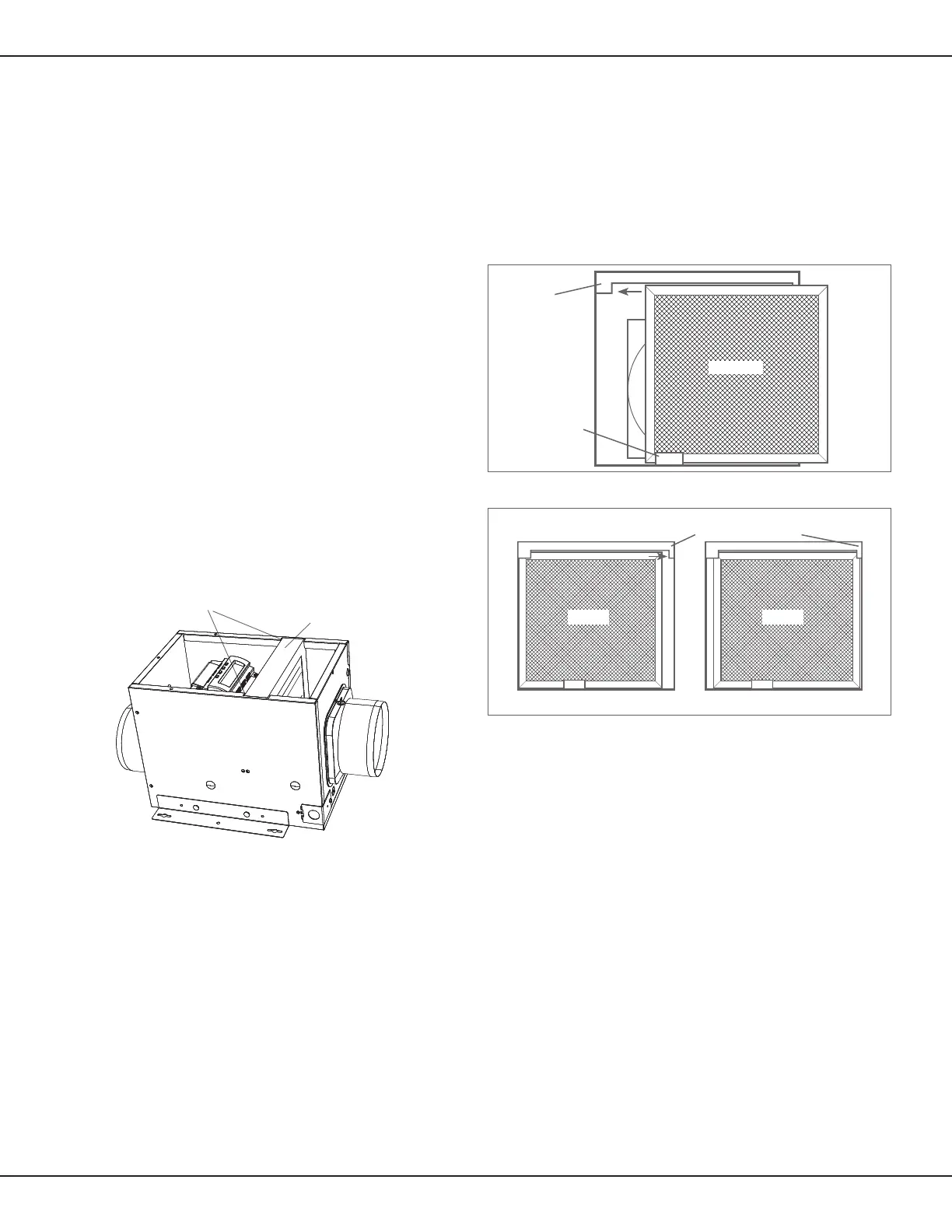
NOTE: This unit is equipped with a wire mesh insect screen.
Conrm that the screen is installed inside the control compartment
just inside the intake port. Posion the screen with its stamped
depression towards the controller.
1. If, when the venlator is unpacked, the insect screen is not in
place, remove the Control Compartment cover (Figure 7) and
insert the screen behind the tab at the base of the unit. Make
sure the wider side of the screen is running side to side inside
the unit (Figure 10).
2. Slide the screen to the side of the cabinet with the larger top tab
making sure the screen ts behind the tab (Figure 10).
Figure 9 - Locaon of oponal air lter
3. Then slide the screen in the opposite direcon and tuck it
behind the smaller tab (Figure 11).
4. Conrm that the screen is being held in place by both top tabs
(Figure 11).
5. Reinstall the control compartment cover and the screws to hold
it in place.
6. Restore power to the venlator and test your installaon.
Figure 11 - Securing the insect screen in place
Filter Slot Channels
Filter (inserted into Slot)
Figure 10 - Installing the insect screen
Base Tab
Screen
Larger Top Tab
Screen
Smaller Top Tab
Screen
 Loading...