Si001270EB PCBs / Electrical Box
Removal Procedure 7
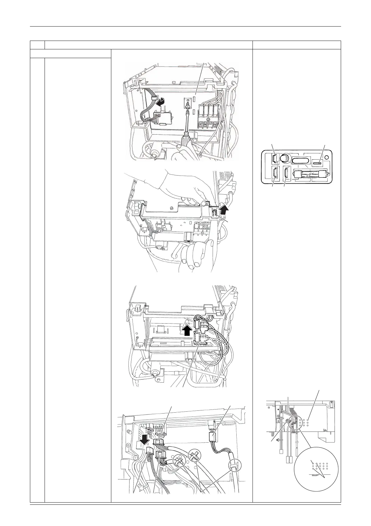
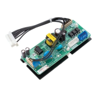
3. Remove the main PCB.
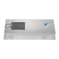
Power supply PCB
[HL]: terminal board
[HE2]: earth / ground wire
[HAC1]: [AC1] on main PCB
[HE1]: [E] on main PCB
The cooling only models do
not have the harness for
[S80].
[S20]: electronic expansion valve
[S40]: overload protector
[S80]: four way valve coil
[S90]: thermistors
When reassembling, insert
each clamp into the holes as
below.
When reassembling, the
thermistor harness should
be placed between the
electrical box and the reactor
harness as below.
1
2
Remove the screw of
the cable way board.
Unfasten the hook and
open the cable way
board.
3
Disconnect the
harnesses from the
power supply PCB.
4
Disconnect the
connectors and pull out
each clamp of the front
side.
Step
Procedure Points
Cable way board
(R19340)
(R19338)
Hook
[HE1]
[HE2] [HL]
[HAC1]
(R17725)
Reactor
harness
Thermistor
ASSY
(R17727)
Reactor harness
Thermistor
ASSY
Electronic
expansion valve
(R17724)
Power supply PCB
[S40]
[S20]
[S80]
[S90] Clamp
(R19339)