SiBE121135_A Wiring Diagrams
Appendix 284
2.2.3 Floor / Ceiling Suspended Dual Type
FLXS25/35/50/60BAVMB
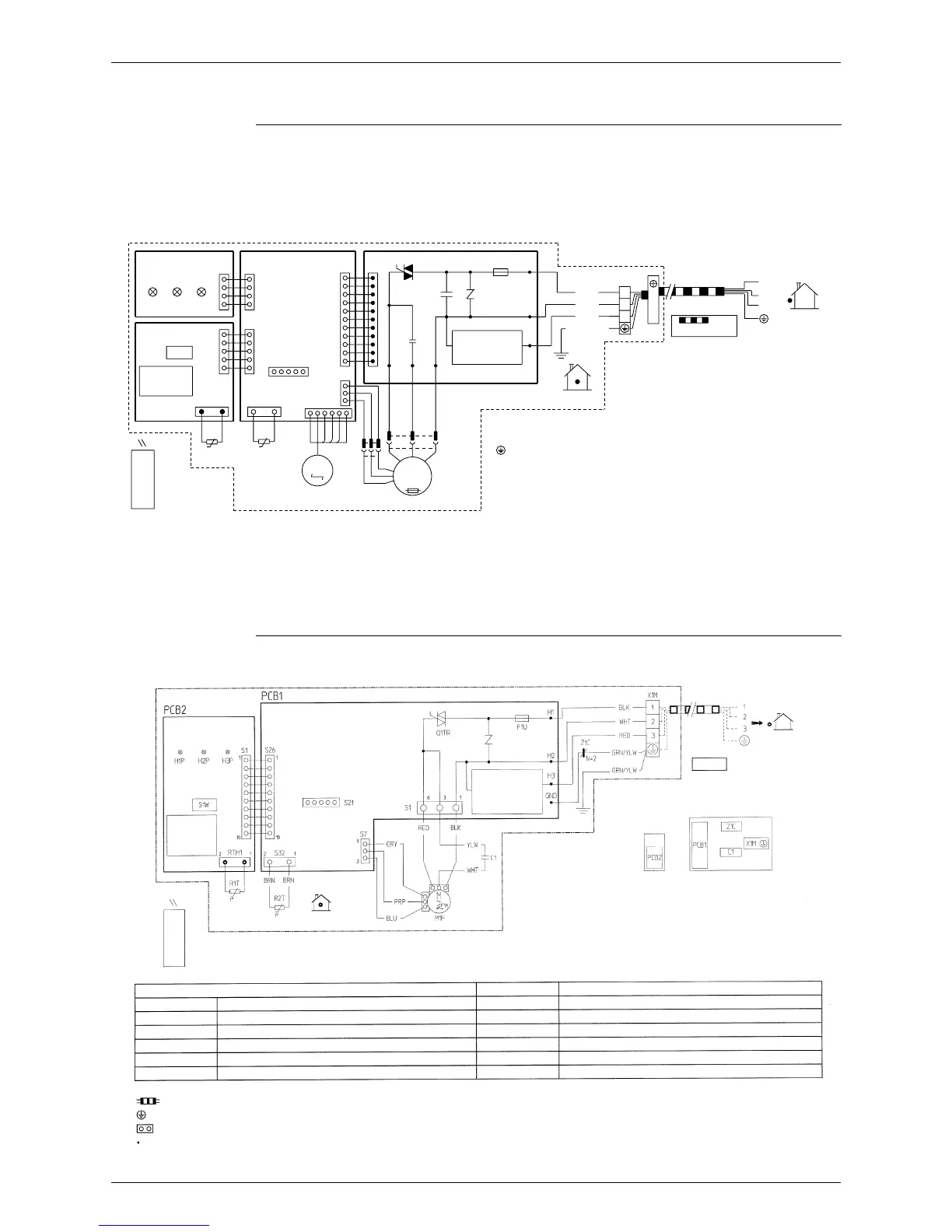
2.2.4 Duct Connected Type
FDXS25/35E7VMB, FDXS50/60C7VMB
LED
H1P
PCB3
LED
H2P
PCB4
S1W
LED
H3P
R1T
S31
t°
S27
S25
S24
S26
S32
R2T
t°
PCB1
S21
HA
M
S6
M1S
S37
S7
X21A
S36
H4
100°C
1~
M
t°
H5
C70
M1F
H6
X11A
PCB2
3.15A
Fu
H2
H3
H1
GRN
WHT
RED
BLK
/
YLW
X1M
2
3
1
CAUTION
2
3
1
→
WIRELESS
REMOTE
CONTROLLER
NOTE THAT OPERATION WILL
RESTART AUTOMATICALLY IF
THE MAIN POWER SUPPLY IS
TURNED OFF AND THEN BACK
ON AGAIN.
SIGNAL
RECEIVER
TRANSMISSION
CIRCUIT
FIELD WIRING.
outdoor
indoor
C70
FU
H1P~H3P
M1F
M1S
: PROTECTIVE EARTH
: RUNNING CAPACITOR
: FUSE
: PILOT LAMP
: FAN MOTOR
: SWING MOTOR
PCB1~PCB4
R1T~R2T
S6~S37, X11A, X21A
S1W
X1M
: PRINTED CIRCUIT BOARD
: THERMISTOR
: CONNECTOR
: OPERATION SWITCH (SW7)
: TERMINAL STRIP
3D033909F
2TW32966-1
Signal
receiver
Terminal for
centralized control
Indoor
Infrared remote control
Signal receiver
Switch box (indoor)
Transmission
circuit
Outdoor
Caution
Operation will restart automatically
if the main power supply is turned
off and then back on again.
C1
F1M
F1U
H1P~H3P
M1F
PCB1
Indoor unit
Capacitor
Thermal protector (M1F Embedded)
Fuse (3.15, 250V)
Light emitting diode
Motor (fan)
Printed circuit board
PCB2
O1TR
R1T, R2T
S1~S32, RTH1
S1W
X1M
Z1C
Signal receiver
Phase control circuit
Thermistor
Connector
Operation switch
Terminal strip
Noise filter (Ferrite core)
: Field wiring
: Protective earth (screw)
: Connector
: Wire clamp
Colors:
BLK:
BLU:
BRN:
GRY:
Black
Blue
Brown
Grey
ORG:
PNK:
PRP:
RED:
Orange
Pink
Purple
Red
WHT:
YLW:
GRN:
White
Yellow
Green