SiBE121135_A Outdoor Unit
Printed Circuit Board Connector Wiring Diagram 46
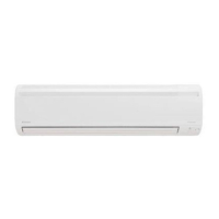
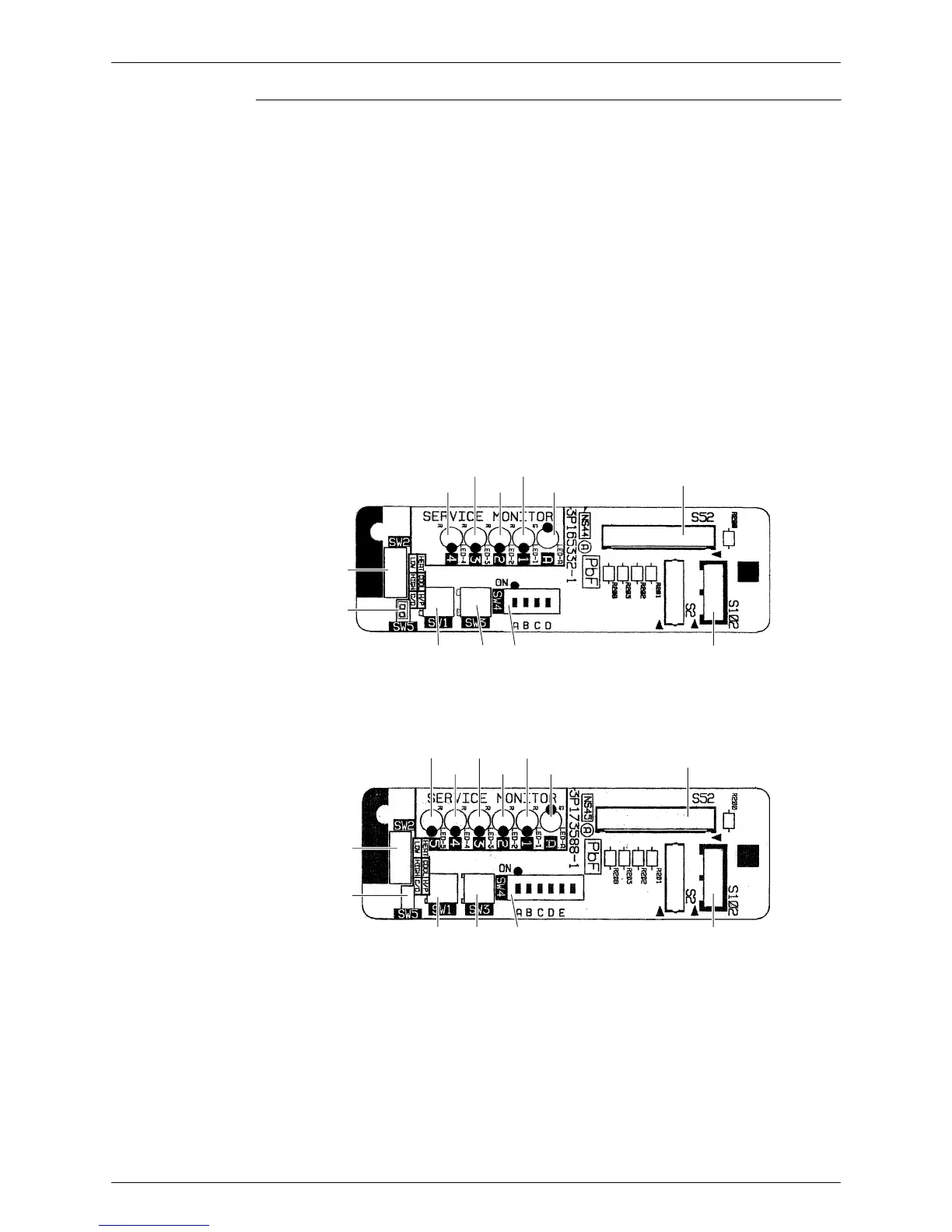
Service Monitor
PCB
for 3 or 4-room model
for 5-room model
1) S52, S102 Connector for main PCB
2) LED A LED for service monitor (green)
3) LED1 - LED4 LED for service monitor (red)
4) LED 5 LED for service monitor (red) (for 5-room model only)
5) SW1 Forced operation [ON/OFF] switch
∗ Refer to page 243 for detail.
6) SW2 Operation mode switch
∗ Refer to page 243 for detail.
7) SW3 Wiring error check switch
∗ Refer to page 244 for detail.
8) SW4 Priority room setting switch
∗ Refer to page 250 for detail.
9) SW5 NIGHT QUIET mode setting switch
∗ Refer to page 252 for detail.
SW2
LED4
LED3 LED1
LED2 LED A
S52
S102SW4SW3SW1
SW5
3P165332-1
SW2
LED4
LED3
LED5 LED1
LED2 LED A
S52
S102SW4SW3SW1
SW5
3P173588-1