SiBE121135_A Indoor Unit
Printed Circuit Board Connector Wiring Diagram 54
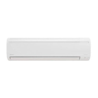
Signal Receiver
PCB
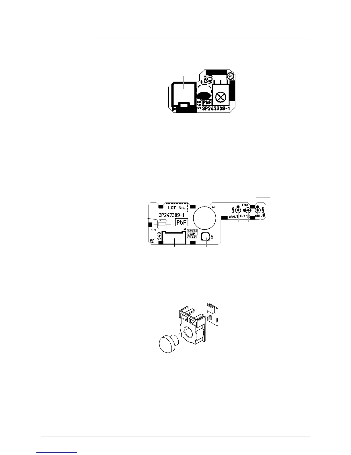
Display PCB
INTELLIGENT
EYE Sensor PCB
1) S48 Connector for control PCB
S48
3P247309-1
1) S49 Connector for control PCB
2) SW1 Forced cooling operation [ON/OFF] button
3) LED1 (H1P) LED for operation (green)
4) LED2 (H2P) LED for timer (yellow)
5) LED3 (H3P) LED for INTELLIGENT EYE (green)
6) RTH1 (R1T) Room temperature thermistor
LED1LED2LED3
SW1S49
RTH1
3P247309-1
1) S36 Connector for control PCB
S36
3P227885-1