SiBE121135_A Indoor Unit
Printed Circuit Board Connector Wiring Diagram 56
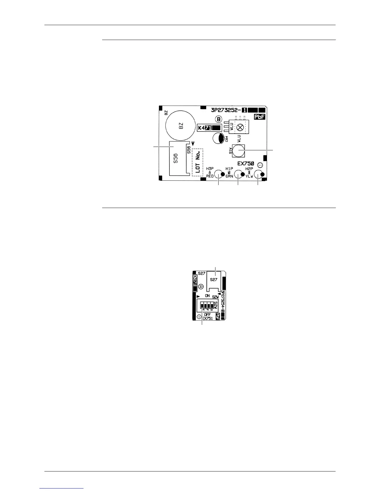
Display PCB
Service PCB
1) S56 Connector for main PCB
2) S1W Forced cooling operation [ON/OFF] button
3) H1P LED for operation (green)
4) H2P LED for timer (yellow)
5) H3P LED for RADIANT operation (red)
S56
S1W
H3P
H1P H2P
3P273252-1
1) S27 Connector for main PCB
2) S2W-1 Address setting switch
∗ Refer to page 253 for detail.
∗ Keep the other switches as factory setting (OFF).
S2W-1
S27
3P273254-1