SiBE121135_A Indoor Unit
Printed Circuit Board Connector Wiring Diagram 62
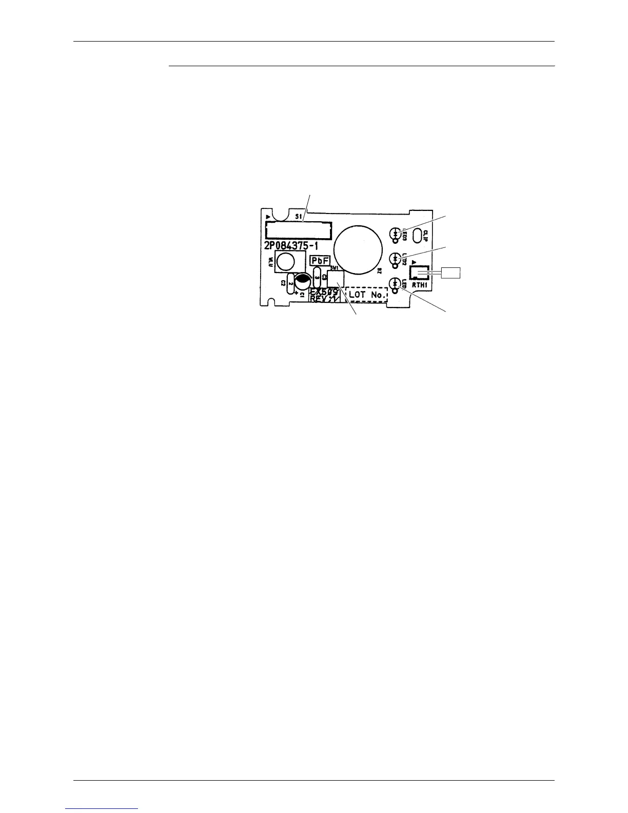
Display PCB
1) S1 Connector for control PCB
2) SW1 (S1W) Forced cooling operation [ON/OFF] button
3) LED1 (H1P) LED for HOME LEAVE operation (red)
4) LED2 (H2P) LED for timer (yellow)
5) LED3 (H3P) LED for operation (green)
6) RTH1 (R1T) Room temperature thermistor
S1
LED3
LED2
LED1
SW1
2P084375-1
RTH1