• Heat reclaim ventilation • VAM-FA/FB
1
15
• Ventilation • Heat reclaim ventilation
70
15 Control systems
15 - 3 Basic patterns
15 - 3 - 2 Independent system
Operation by main switch
Purposes and functions
• Basic method to operate HRV unit
The remote control for HRV unit is installed on each HRV
unit for its operation.
[When you use remote control for HRV unit]
Cautions
1. The remote control for HRV unit should be connected to the
terminal no. P1 and P2.
2. The remote control wiring should be arranged locally.
3. The operation by two remote controls or the group control
is not possible.
4. The initial setting cannot be done by the remote control for
HRV unit, which has to be set by the remote control for
indoor unit.
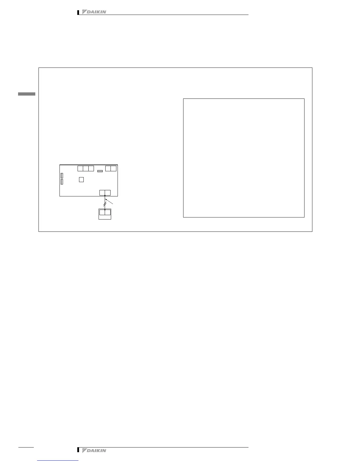
Example of control wiring
Switch setting of HRV unit
• No change is required (as per factory setting)
Optional accessories required
• Remote control for HRV unit BRC301B61
Information
1. If you increase the air flow rate from “High” to
“Ultra-High” by the remote control for HRV unit,
it is necessary to have initial setting by the
remote control for indoor unit or HRV unit.
(HC0022)