3
1
15
• Ventilation • Heat reclaim ventilation
71
• Heat reclaim ventilation • VAM-FA/FB
15 Control systems
15 - 3 Basic patterns
15 - 3 - 2 Independent system
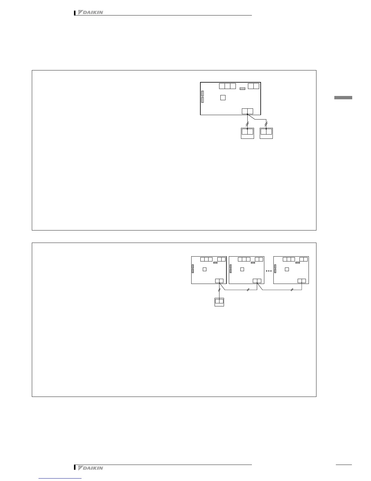
Control with two remote controls
Group control
Purpose and functions
• For control of one HRV unit (Also one group control is
possible)
Sophisticated operation and indication output are possible
from either local place or remote place by two liquid crystal
remote controls.
• Either one of two liquid crystal remote controls can be used
for all operations and indications.
(However, initial setting can only be carried out by the
master remote control)
Point
• The wiring to the remote controls must be branched from the
unit as shown in the diagram.
(Though the crossover between the master and slave
remote controls is acceptable, the work to put two wires into
the remote control takes time.)
Example of wiring for control
Note
1. The maximum allowable total length of wires to the remote
control is 500 m.
2. Simple remote controls cannot be used for control with two
remote controls.
The following setting is required
• Either one of two remote controls must be set as a slave
remote control.
Required optional accessories
• Liquid crystal remote control × 2
BRC301B61
Purpose and functions
• Simultaneous control of multiple HRV units (max. 16 units) is
available (for application to such as a spacious room)
• All operation and individual setting can be carried out from
one remote control.
• In case the liquid crystal indicates malfunction, the indication
of HRV unit No. shows in the display.
(If another remote control is additionally installed, control
with two remote controls is possible.)
Point
• No address setting is required because address is
automatically set.
(The address is optionally allocated. The address No. can
be confirmed by setting to service mode “Forced fan
operation” and be checked whether the unit is in operation
or not.)
Example of wiring for control
Note
1. The maximum allowable total length of wires to the remote
control is 500 m.
2. One liquid crystal remote control is always required.
3. Simple remote controls cannot be used for control with two
remote controls.
The following setting is required
• No setting is required. (product is to be just as it was when
shipped from the factory)
Required optional accessories
• One set of liquid crystal remote control
BRC301B61