• Heat reclaim ventilation • VAM-FA/FB
1
15
• Ventilation • Heat reclaim ventilation
80
15 Control systems
15 - 4 Applicable patterns
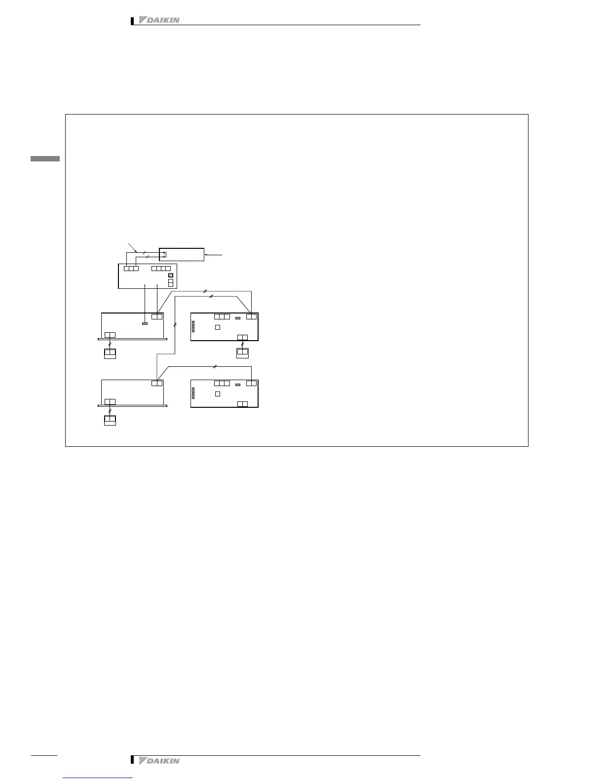
15 - 4 - 3 Central control system (DCS302B61)
Collective operation [Adapter PCB for remote control KRP2A Series]
Purposes and functions
A maximum of 64 groups can be controlled the operation of “ON /
OFF” collectively. (For the individual control, use the central
remote control or the unified On / Off control.)
Cautions
1. Adapter PCB can be installed in any unit connected to the
central transmission line.
2. It cannot be used with other central control.
3. The setting of group number is not required.
4. The HRV unit judges the ventilation mode, individually.
Example control wiring
Switch setting of the HRV unit
The initial setting is required by the remote control for the indoor
unit or HRV unit.
• Collective zone interlock setting
......................................“OFF” (as per factory setting)
• The setting of switch on the PCB
• Voltage / no-voltage changeover switch(SS1)
......................................“no-voltage”
* Remote control mode changeover switch (RS1) should be
selected.
Optional accessories required
Adapter PCB for remote control KRP2A61