3
1
15
• Ventilation • Heat reclaim ventilation
81
• Heat reclaim ventilation • VAM-FA/FB
15 Control systems
15 - 4 Applicable patterns
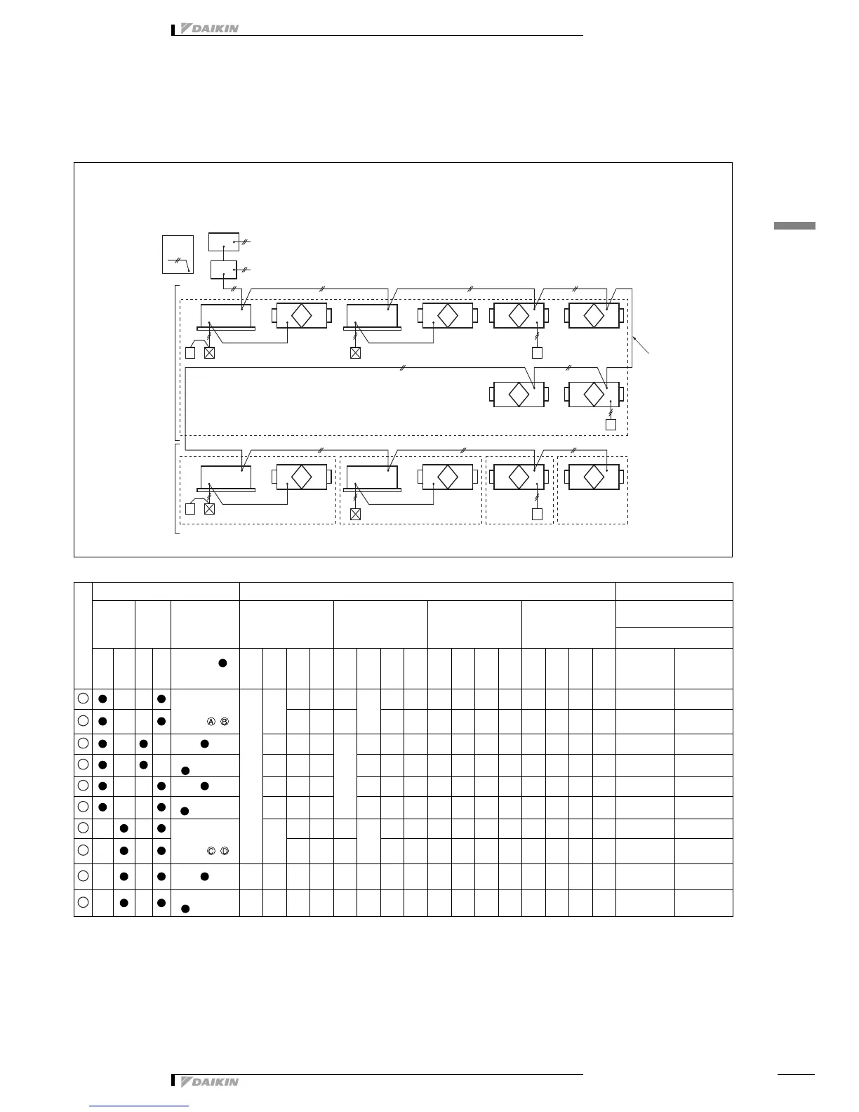
15 - 4 - 3 Central control system (DCS302B61)
Multi function central control + Unified On / Off Control
*1. Independent operation for ventilation is possible, if collective zone interlock setting is “ON” with the indoor unit in the same zone.
*2. It is possible by the initial setting.
*3. Display of malfunction code only.
*4. The meaning of total evaluation
AA: Interlocked operation with energy saving and changeable of Ventilation mode / Air flow rate
BB: Interlocked operation with energy saving and no changeable of Ventilation mode / Air flow rate
CC: No interlocked operation with energy saving and changeable of Ventilation mode / Air flow rate
DD: No interlocked operation with energy saving and no changeable of Ventilation mode / Air flow rate
*5. Interlocked operation setting must not be done for individual zone. (Because there is no unit to combine in zone except 1unit.)
Proper control should be selected according to the functions required.
System description
Unit No.
Setting Operation display functions (
means possible) Choise condition
Zone
setting
Interlocked
zone contol
Group number
setting for
central control
Operation / stop
Independent ventilation
Operation/stop
Ventilation air flow
Ventilation mode
Fresh-up
Filter-sign
Malfunction code
HRV unit side
Collective
Individual
On Off
Required ( )
Not Required
RC1
RC2
RSA - D
R1 - 9
RC1
RC2
RSA - D
R1 - 9
RC1
RC2
RSA - D
R1 - 9
RC1
RC2
RSA - D
R1 - 9
Interlocked
operation with
Energy saving
*4
Total
evaluation
Not required
(Setting required
only for )
Collective by zone
Linked to
A / B
— —
Linked to
A / B
— — — —
— — —
AA
— —
— — — *2 — *3 — *3 —
AA
—
—
*1
—
— — — —
— —
AA
(Connection required,
when setting)
—
— —
— — — — —
— — —
BB
—
—
— — —
— —
— CC
(Connection required,
when setting)
— —
— — — — — —
— — — — DD
Not required
(Setting required
only for )
Linked to
C / D
— —
Linked to
C / D
— — — —
— — —
AA
— —
— — — *2 — *3 — *3 —
AA
—
—
— — —
— —
—
*5
CC
(Connection required,
when setting)
— —
— — — — — —
— — — —
*5
DD