• Heat reclaim ventilation • VAM-FA/FB
1
15
• Ventilation • Heat reclaim ventilation
82
15 Control systems
15 - 4 Applicable patterns
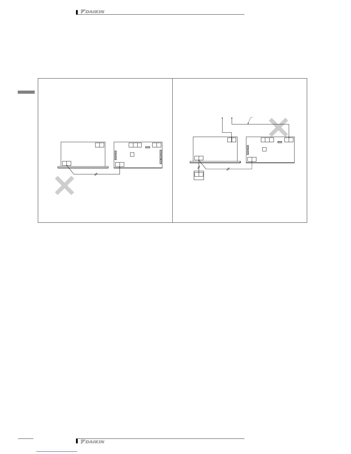
15 - 4 - 4 Examples of mistakes in wiring and system designing
It is necessary to install the remote control for
the transmission line.
The centralized transmission line should be connected to
the indoor unit.
<Part 1>
• When you connect the transmission line for the remote
control, the remote control should be installed on the
transmission line.
Example of control wiring
Reason
Because the signal through the transmission line is originated
from the remote control, there is no transmission signal to operate
the units, if the remote control is not installed.
<Part 2>
• If the HRV unit is interlocked to the centralized control, the
central transmission line should be connected to the terminal
no. F1 and F2 of indoor unit.
Example of control wiring
Reason
The information from the indoor unit cannot be transmitted to the
central control through the HRV unit. And also the information
from the central control cannot be transmitted to the indoor unit
through the HRV unit.