Accessories ED34-862
98 FXFQ-P
JC : 3K017588C
|PS<
2
Bell mouth
Indoor unit main body
455mm
Partition plate
14
Suspension bracket
Duct (arrangement at site)
*1
Suction chamber
A
Indoor unit
main body
Indoor unit main body
Bell mouth
Tape for fixing the sealing material
14
(12)
725
Sensor assembly
7
Hook
Fixing screw
9
(12)
A
Control box cover
Clamp
8
Inspection opening ( 450 or more)
Sensor assembly
7
Corner air outlet sealing material
4
1
5
Release paper
Refrigerant piping
Sensor assembly
M5 × 12
Part number
4
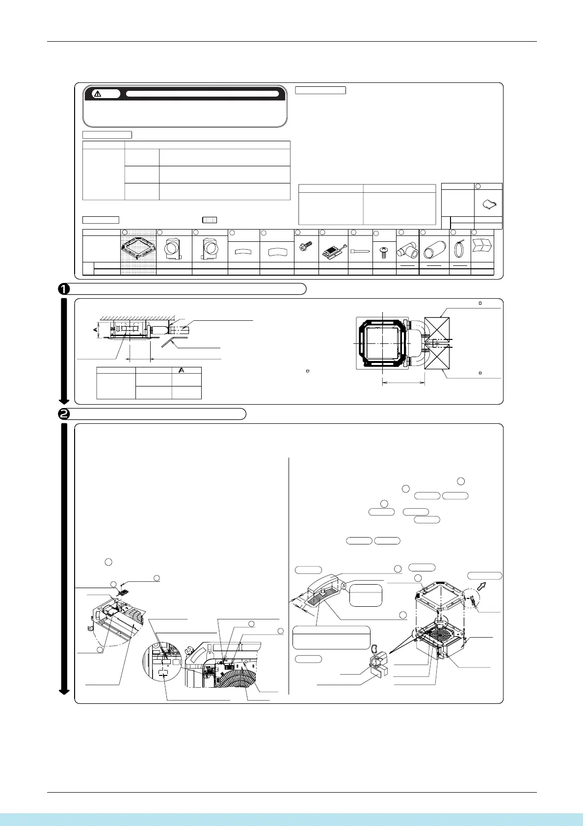
Check the following parts. (Shaded part is included in a different package.)
13
Installation manual
Installable indoor unit / Panel model name
KDDP55K160 (K)
Flexible duct
(Nominal diameter φ150)
Figure 1
Figure 2
Figure 3
To Figure 4
K-FDS151D (1m)
K-FDS152D (2m)
K-FDS153D (3m)
K-FDS154D (4m)
KDDP55K160K
classes 28 to 90
classes 112 to 160
1
Suction chamber
2
Procedure 1
2
1
2 1
6
Mounting screw
Name
(4 positions)
Shape
11
WHITE
KDDP55K160
1
Selection of Installation Location and Establishment of Inspection Opening
11
(mm)
1 1
Partition plate
Mounting of Sensor Assemblies and Suction Chamber
Caution
2
Connecting chamber (left)
4
12
Sealing pad
22
2
Part name
Indoor unit
1
1
Name
(this document)
(2) Establish an inspection opening.
Model name
Combination table
7
Sensor assembly
8
Clamp
4
KDDP55K160K
1
1
Shape
(4 positions)
306
After thoroughly reading these "Safety precautions", properly perform the installation.
• For the installation parts, accessory parts and specified components must always be used.
If the specified components are not used, the kit may fall or an air leak may occur.
• After the completion of installation, perform a test run to check that no abnormality is present.
(1) Refer to the figure below to select the installation location.
BYCP125K-W1
3
Connecting chamber (right)
Parts content
<Mounting of sensor assembly>
<Mounting of suction chamber>
X16A
348
11
T joint
10
Flexible duct
Recommendations
1 1 2
KDDP55K160
· This product can be mounted to a ceiling mounted cassette-type air conditioner
<Round flow>.
·
According to the table to the left, check the model name of the indoor unit, then mount the kit.
· At the time of mounting, also refer to the installation manual for the indoor unit and to the
one for the decoration panel.
· When mounting the duct fan, be sure to use the wiring modification adaptor [KRP1C63] to
interlock with the indoor unit fan.
For the intake wind volume, 10% or less of the indoor unit wind volume of "H" is
recommended.
When the intake wind volume becomes excessive, operation noise may become louder or
the intake temperature detection of the indoor unit may be affected.
· Be sure to mount the supplied sensor assembly.
<For the duct used for field connection, those in the table below are recommended.>
Number
of pieces
Number
of pieces
4
Corner air outlet
sealing material
5
Corner air outlet tape for
fixing the sealing material
9
Mounting screw
(for sensor)
Inspection opening
(ceiling opening
dimension)
*1. Install the suspension bracket for
the T joint section.
Because of the load from T joint,
etc., a gap may be created in
between the indoor unit and
suction chamber.
*2. Establish an inspection opening ( 450 or more).
Establish an inspection opening to either side.
(Refer to *2.)
Inspection opening ( 450 or more)
(Refer to *2.)
* When the indoor unit main body is already installed, perform the following operations, complying with precautions below.
•
Shut off power supply before performing operation.
•
Remove the decoration panel from the indoor unit main body.
(For details, refer to the installation manual attached to the decoration panel.)
(1) According to the installation manual attached to the indoor unit main
body, remove the cover of the control box.
(2) Using the supplied screws, tighten the sensor assembly together with
the bell mouth to the indoor unit main body.
(Mount without pinching the float switch lead wire.)
(3) Remove the connector (X16A) of the existing sensor from the PC
board of the indoor unit main body.
(4) Connect the lead wire of the mounted sensor assembly to the
connector (X16A) on the PC board of the indoor unit main body as
shown in the figure below.
(5) As shown in the figure below, fix the lead wire using the supplied
clamp.
(6) After all the wiring is completed, fit the control box cover according to
the installation manual attached to the main body.
(7) Making sure that the control box cover is covered with the partition
plate , tighten these together using the screws on the cover. (Hook
the partition plate tab onto the cover.)
14
* Figure shows an example where the indoor unit main body is newly
installed.
(1) Stick the corner air outlet tape for fixing the sealing material to
the corner air outlet sealing material , then stick it to the air outlet
of the indoor unit main body. (2 positions)
(2) Mount the suction chamber to the indoor unit main body using
the hook (4 positions). to
For the fixing method of the hook, refer to , then mount at
4 positions.
* Mount so that the contours of the indoor unit main body and suction
chamber match.
1
5
4
Figure 1
Figure 3 Figure 5
Figure 4
Figure 4 Figure 6
Figure 2
(7) Using screws, tighten the
partition plate together with
the control box cover so that
the box cover is covered
with the partition plate.
Control box cover
(1) Remove the control box
cover. (Screws at 2 positions)
(2) Using the supplied
screws, tighten the
sensor assembly
together with the bell
mouth.
(5) Tighten with the
existing wiring.
(4) Connect the connector of the
mounted sensor assembly.
(5) Tighten with the float switch
lead wire of the indoor unit
main body.
(3) Disconnect the connector of
the existing sensor.
Float
switch
lead wire
Remove the
release paper.
Procedure 2
Stick the sealing material to the tape for
fixing the sealing material. (2 pieces)
Air outlet
* The figure
shows SkyAir
For 2 positions
BYCP125K-W1
FCQ(N)71·100·125·140KVEA
Panel
SkyAir
VRV FXFQ25~125PVE
Все каталоги и инструкции здесь: http://splitoff.ru/tehn-doc.html






 To Next Page