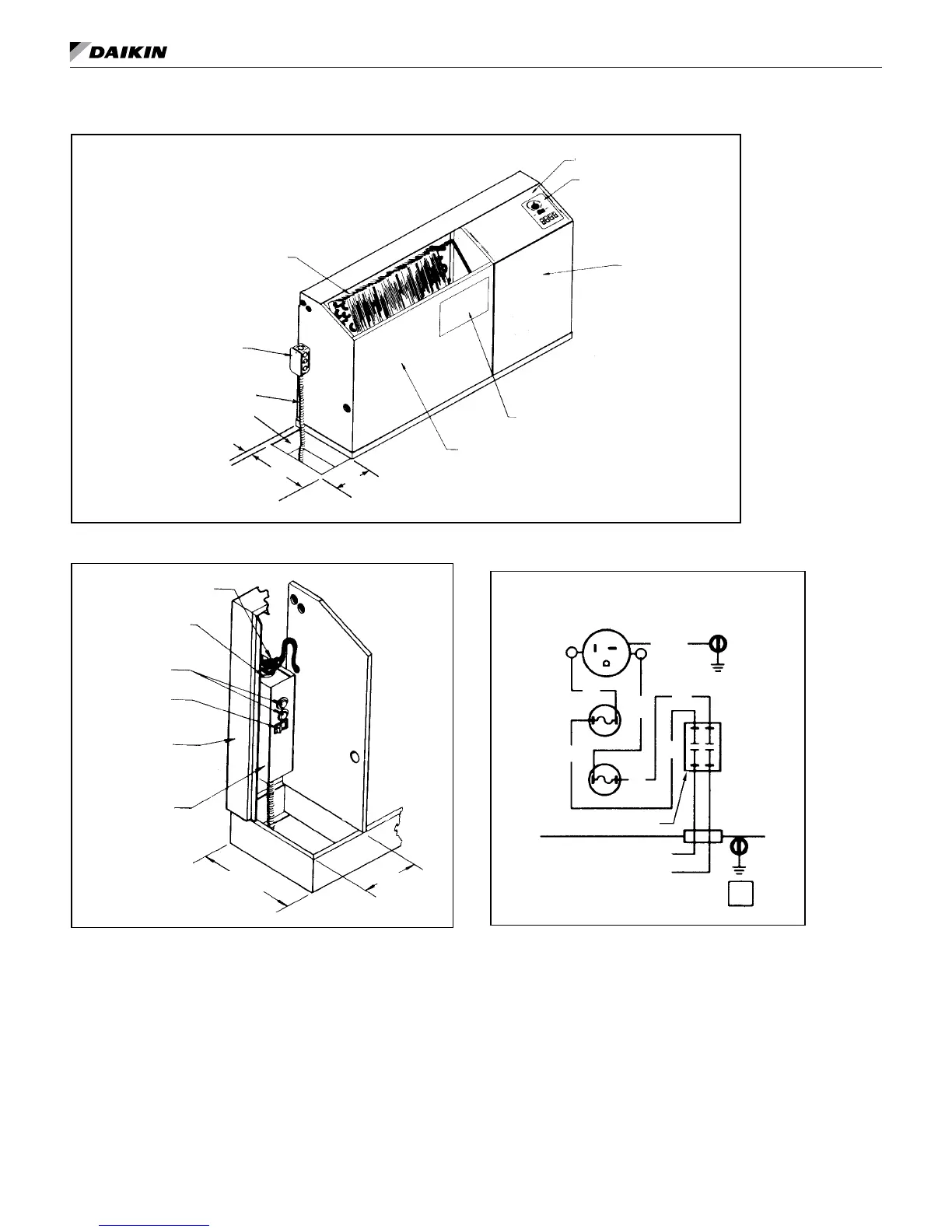
Figure 7: Standard electrical connection - Junction box
Air Coil
5.0"
Control Box
Escutcheon Plate
Compressor Cover
Wiring Diagram
Fan Motor Cover
(127mm)
9.0"
(229mm)
1.0"*
(25mm)
*1.0" (25mm) from inside
surface of wall
Electrical Conduit
Floor
Junction Box
Figure 8: Cord & plug connection (field-installed)
Power Cord
Receptacle Plug
Fuse Holder
Switch
Backwrap
Fuse
Disconnect Box
10.0"
(254mm)
5.00"
(127mm)
Figure 9: Cabinet power connection (field-installed)
Receptacle, Fuses & Disconnect Switch
(Requires plug cord on chassis.)
Fused Disconnect Box
Wire Diagram 61408101
WH or RD
BK
BK
Fuse
RECEPTACLE
GR/YE
PK
PK
Fuse
REV
0
Disconnect Switch
BK
WH
WH
IM 447-11 12 www.DaikinApplied.com