Field Installed Outside Air Damper (Accessory)
CAUTION
To prevent inltration of ambient conditions, it is the responsibility of the contractor to assure that factory installed gasketing matches up with
the wall opening, or that additional material is used to assure a positive seal. Cold Weather Operation: Console water source heat pumps may
experience erratic operation during cold ambient conditions with the outside air damper in the open position. Refer to the “Operating Limits”
in the unit catalog 1140-x.
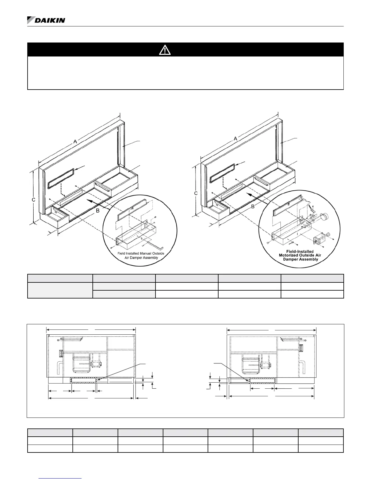
Manual Outside Air Damper
Figure 18: Rear inlet - typical manual damper installation
Backwrap
Subbase
*10"
(245mm)
Gasket
Motorized Outside Air Damper
Figure 19: Rear inlet - typical motorized damper installation
Backwrap
Subbase
*10"
(245mm)
Gasket
Table 10: Dimensions, in inches (mm)
Unit Type Unit Size A B C
Standard Height
009-012 46 (1168) 45 (1143) 25 (635)
015-019 54 (1372) 53 (1346) 25 (635)
Note: *Total unit is 10-3/4″ deep. The cabinet extends beyond the subbase 1/4″ (6mm) in the back and 1/2″ (14mm) in the front.
Figure 20: Left-hand & right-hand views
Table 11:
Front View - Right Hand Piping
Back Panel With Outside Air Damper Inlet
A
C
1
D
B
.50" (13mm)
Gasket
.62"
(16mm)
.50" (13mm)
2.25" (57mm)
Opening
Gasket
Gasket
.62"
(16mm)
.50" (13mm)
A
D
C
B
Front View - Left Hand Piping
Back Panel With Outside Air Damper Inlet
Outside air damper opening location
Unit Size A B C C
1
D E
009 - 012 46 (1168) 45 (1143) 21.09 (536) 11.38 (289) 12.53 (318) 2.25 (57)
015 - 019 54 (1372) 53 (1346) 22.25 (565) 22.25 (565) 12.53 (318) 2.25 (57)
www.DaikinApplied.com 21 IM 447-11