www.DaikinApplied.com 11 IOM 1274-3 • CENTRIFUGAL WATER CHILLERS
damage or water side damage to the chiller heat exchangers
due to improperly treated water.
during initial chiller installation/commissioning and maintained
on a continuous basis by water treatment professionals (see
Limited Product Warranty).
CAUTION
The improper use of detergents, chemicals, and additives
performance and potentially lead to repair costs not covered
by warranty. Any decision to use these products is at the
discretion of the owner/occupant/operator/user and as such
they assume full liability/responsibility for any damage that
may occur due to their use.
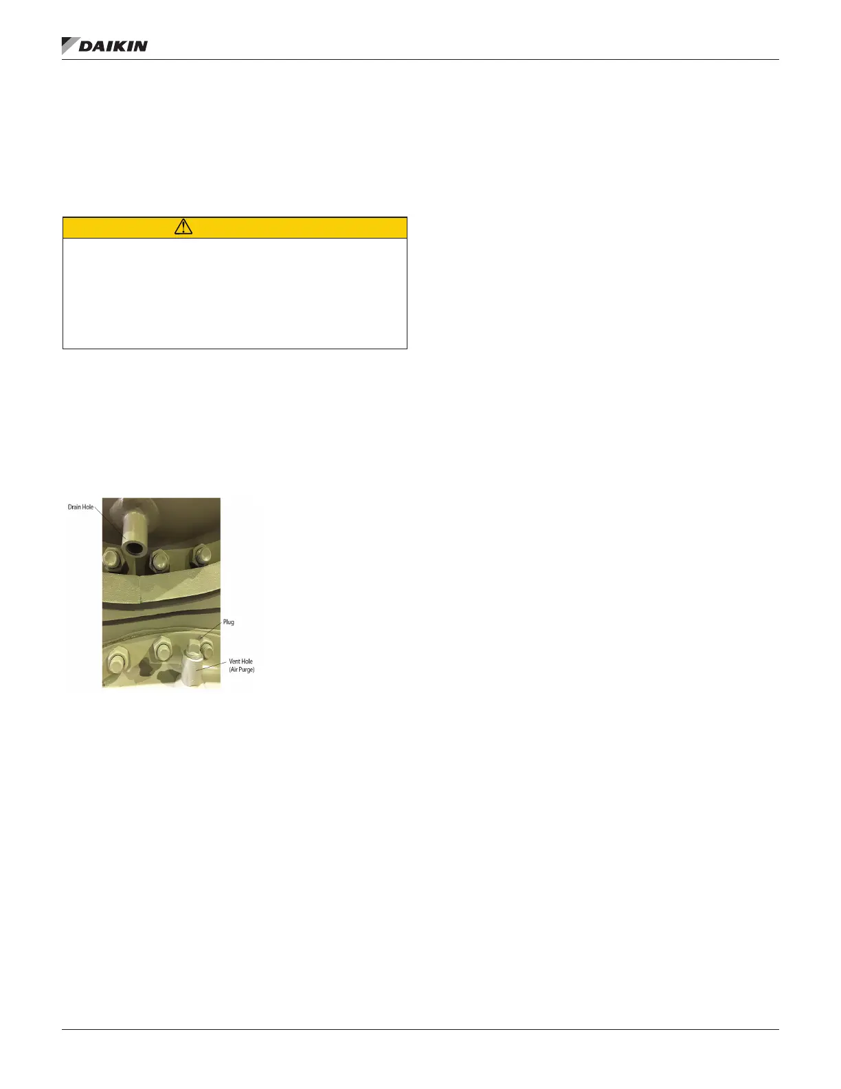
Vessel Drains at Startup
The unit is drained of water at the factory. Drain plugs for each
vessel head are shipped separately in the control box. Units
are shipped with the drain plug in the top water box drain hole
and no plug in the bottom drain hole. Install the bottom drain
Figure 4.
Figure 4: Drain Plug Installation
Flow Switches
wired. See the Field Wiring Diagram on page 32 or on the
cover of the control panel for proper connections. The purpose
until such time as both the evaporator water and condenser
started. See
69 for further information.
Variable Fluid Flow Rates
power, and potential tube erosion or corrosion damage.
be avoided as they will result in poor heat transfer, high
compressor power, sedimentation and tube fouling.
rate should not exceed 50% of the current value per minute.
should use 10% of the current value per minute as guidance.
All chilled water systems need adequate time to recognize a
load change, respond to that load change and stabilize, without
undesirable short cycling of the compressors or loss of control.
In air conditioning systems, the potential for short cycling
usually exists when the building load falls below the minimum
chiller plant capacity or on close-coupled systems with very
small water volumes.
Some of the things the designer should consider when looking
at water volume are the minimum cooling load, the minimum
chiller plant capacity during the low load period and the desired
cycle time for the compressors.
Assuming that there are no sudden load changes and that
the chiller plant has reasonable turndown, a rule of thumb of
“gallons of water volume equal to two to three times the chilled
A properly designed storage tank should be added if the
Operation of the chilled water pump can be to 1) cycle the
pump with the compressor, 2) operate continuously, or 3) start
automatically by a remote source.
The cooling tower pump must cycle with the machine. The
holding coil of the cooling tower pump motor starter must be
rated at 115 volts, 60 Hz, with a maximum volt-amperage rating
of 100. A control relay is required if the voltage-amperage
rating is exceeded. See “Figure 16: Centrifugal Field Wiring
or in the cover of control panel for
proper connections.
All interlock contacts must be rated for no less than 10
inductive amps. The alarm circuit provided in the control center
utilizes 115-volts AC. The alarm used must not draw more than
10 volt amperes.
Condenser Water Control
Condenser water control is an important consideration in chiller
plant design since condenser water temperature will directly
wet bulb temperature is lower than peak design, the entering
condenser water temperature from the cooling tower can
be allowed to fall, improving chiller performance. However,
operational issues may occur when the condenser water
temperatures are either too high or too low. The WSC chiller