IOM 1274-3 • CENTRIFUGAL WATER CHILLERS 8 www.DaikinApplied.com
Location
The chillers are designed for indoor installation only. Special
procedures must be executed to prevent damage if freezing
indoor temperatures are possible.
NOTE: Excessive humidity in the mechanical room should
be avoided. A limit of 90% non-condensing humidity
should be met to minimize electrical components
exposure to water condensing in panels. Humidity
levels in the mechanical room, even if lower than
90%, can cause water to condense on/near all cool
surfaces and potentially lead to premature component
wear. If possible, the mechanical room should be
conditioned which can extend the useful lifetime for
all mechanical room equipment.
Radiant heat from boilers or piping that would
adversely raise component surface temperatures
beyond ambient limits must also be avoided.
Table 1: Equipment Room Guidelines
WSC - HSC - TSC
R-513A R-134a
Equipment room operating temperature: 40-104 °F (4.4-40 °C)
Equipment room temperature, standby,
with water in vessels and oil cooler:
40-104 °F (4.4-40 °C)
Equipment room temperature, standby,
without water in vessels and oil cooler:
0-113 °F (-17.7-45 °C)
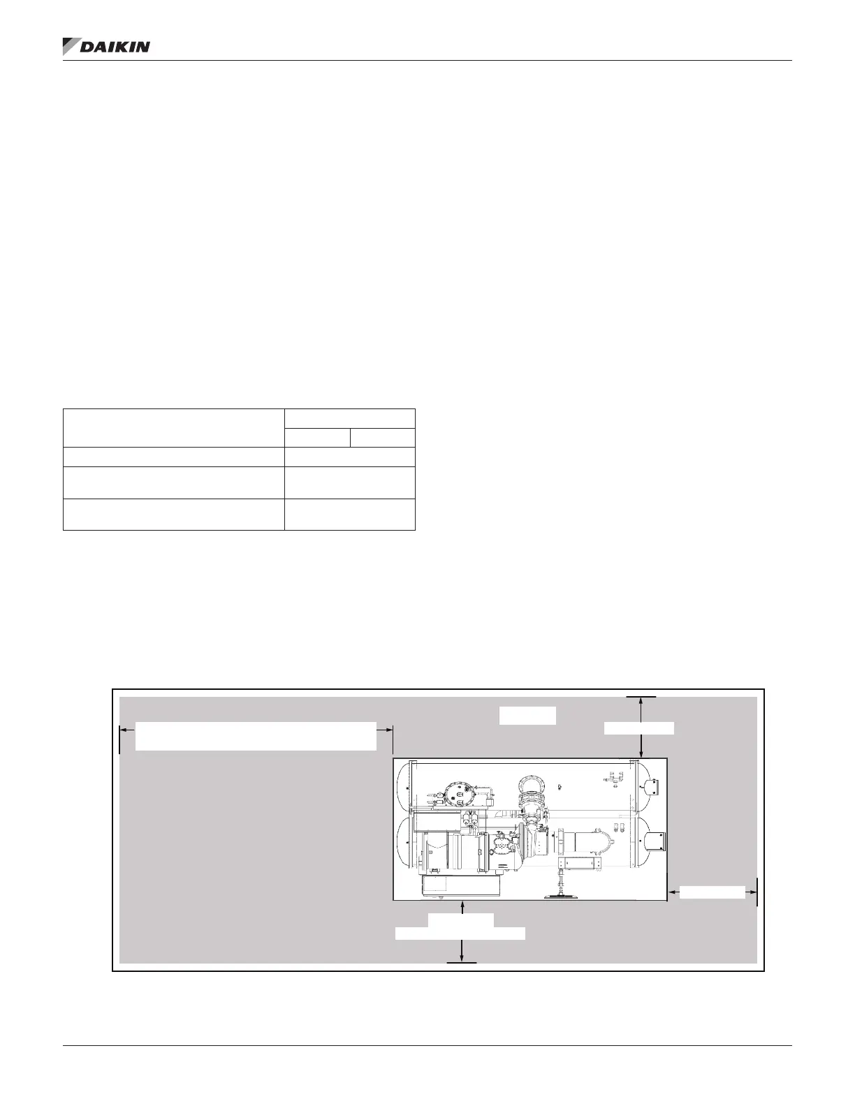
Clearance
The unit must be located to provide adequate service
clearance around the unit. See Figure 3 for clearance
requirements around the sides of the chiller, including the
length of the vessels allowed at one end for tube service.
Doors and removable wall sections can be utilized to meet
these clearance requirements. There must be a minimum
3-feet clearance above the top of the chiller. The U.S. National
Electric Code (NEC) or local codes can require more clearance
in and around electrical components and must be checked for
compliance.
Mounting
The unit must be mounted on a level concrete or steel base.
support the full operating weight of the complete unit.
It is not necessary to bolt the unit to the mounting slab or
mounting holes are provided in the unit support at the four
corners.
NOTE: Units are shipped with refrigerant and oil valves
must remain closed until start-up by the Daikin
Applied technician.
The neoprene vibration pads (shipped loose in the power
panel) should be placed under the corners of the unit (unless
single compressoessor units have six mounting feet although
only the outer four are required. Six pads are shipped and the
installer can place pads under the middle feet if desired.
When mounted, the base pad of the unit must be level to within
± 1/2 inch (12.7 mm) across the length and width of the unit.
Figure 3: Minimum Clearances Based on Standard Waterboxes - Representative Schematic
NOTE:
Daikin Applied sales representative for details.
Minimum 13’ Clearance on one end for tube service (models with 12‘ length vessels)
Minimum 17’ Clearance on one end for tube service (models with 16’ length vessels)
TOP VIEW
Minimum 3’ Clearance
Minimum 3’ Clearance
Minimum 4’ Clearance
in front of control boxes and electrical panels