www.DaikinApplied.com 9 IOM 1274-3 • CENTRIFUGAL WATER CHILLERS
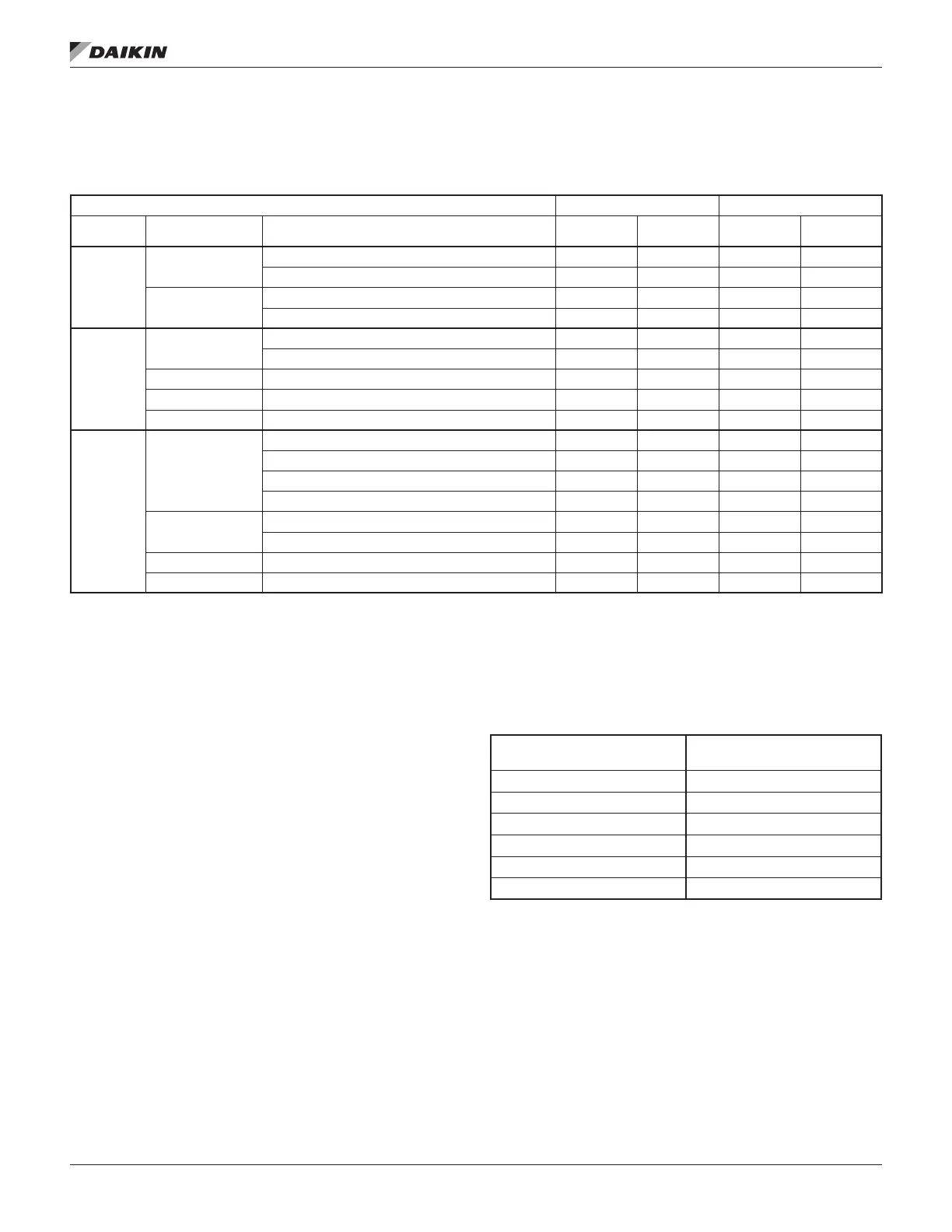
Table 2: Operating/Standby Limits
1
R-513A R-134a
Condition Description
°F (°C)
°F (°C)
°F (°C)
°F (°C)
Standby
Evaporator
Entering Fluid 35 (1.7) 86 (30) 35 (1.7) 90 (32.2)
Entering Fluid w/ Antifreeze
2
20 (-6.7) 86 (30) 20 (-6.7) 90 (32.2)
Equipment Room
Air w/ Water in Vessels & Oil Cooler 40 (4.4) 104 (40) 40 (4.4) 104 (40)
Air w/ no Water in Vessels & Oil Cooler 0 (-17.8) 0 (-17.8) 0 (-17.8) 113 (45)
Startup
Evaporator
Entering Fluid 38 (3.3) 100 (37.8) 38 (3.3) 100 (37.8)
Entering Fluid w/ Antifreeze
2
20 (-6.7) 100 (37.8) 20 (-6.7) 100 (37.8)
Condenser Entering Fluid 35 (1.7) 110 (43.3) 35 (1.7) 111 (43.9)
Oil Cooler Entering Fluid 35 (1.7) 80 (26.7) 35 (1.7) 80 (26.7)
Equipment Room Air 40 (4.4) 104 (40) 40 (4.4) 104 (40)
Operating
Evaporator
Entering Fluid 38 (3.3) 86 (30) 38 (3.3) 90 (32.2)
Leaving Fluid 38 (3.3) 60 (15.6) 38 (3.3) 60 (15.6)
Entering Fluid w/ Antifreeze
2
20 (-6.7) 86 (30) 20 (-6.7) 90 (32.2)
Leaving Fluid w/ Antifreeze
2
20 (-6.7) 60 (15.6) 20 (-6.7) 60 (15.6)
Condenser
Entering Fluid 55 (12.8) 104 (40) 55 (12.8) 105 (40.6)
Leaving Fluid See Note
3
110 (43.3) See Note
3
111 (43.9)
Oil Cooler Entering Fluid 35 (1.7) 80 (26.7) 35 (1.7) 80 (26.7)
Equipment Room Air 40 (4.4) 104 (40) 40 (4.4) 104 (40)
NOTES:
1
heat recovery mode limits)
2
Antifreeze temperature limits must have appropriate glycol concentration
3
Field Insulation
If the optional factory-installation of thermal evaporation
to reduce heat loss and prevent condensation from forming.
Insulation should cover:
• the evaporator barrel, tube sheet, and waterboxes.
• the suction line from the top of the evaporator to the
• the compressor support brackets welded to the
evaporator.
• the liquid line from the expansion valve to the evaporator
inlet, including the expansion valve.
• the part load balance valve to the evaporator.
Approximate total square footage of insulation surface required
for individual packaged chillers is tabulated by code and can
be found in Table 4. Condenser references included for TSC
model units only.
Table 4: Insulation Area Required for Vessels
Vessel Code Insulation Area
E2612 / C2612 102 (9.4)
E3012 / C3012 115 (10.6)
E3612 / C3612 129 (11.9)
E4212 / C4212 148 (13.7)
E4216 / C4216 264 (24.5)
E4816 / C4816 302 (28.1)
Water Piping
All evaporators and condensers have OGS-type grooved water
connections (adhering to Standard AWWA C606) or optional
matching mechanical connections. Be sure that water inlet
markings. PVC piping should not be used.