IOM 1274-3 • CENTRIFUGAL WATER CHILLERS 48 www.DaikinApplied.com
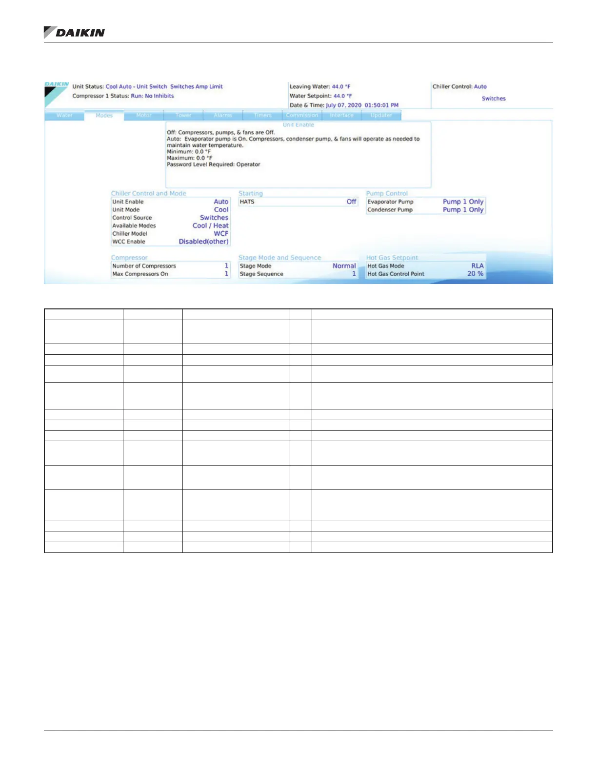
Figure 54: Settings View - Modes
Table 14: Modes Setpoints
Description Default Range PW
Chiller Model WCF WCF, WMC T
WCF is the general software model for WSC (HSC), WDC, WCC, TSC,
and TDC. Heat Recovery option is enabled on Commission tab shown in
Figure 72 on page 57.
WCC Enable Disabled (other) Enabled (WCC), Disabled (other) T Will always be Disabled for WSC chillers
Control Source Switches Switches, Local, Network BAS O Sets control source. See .
Unit Enable OFF OFF, AUTO O
as required to meet LWT
Available Modes Cool/Heat
Cool Only, Cool w/ Glycol, Cool/
Ice w/ Glycol, Ice Only w/ Glycol,
Cool/Heat, Heat Only
M See Water Setpoints,Figure 52, for control temperature targets for each mode
No. of Compressors 1 1 to 2 T WSC models will be set to 1. Any other value will be ignored.
Max Compressors On 2 0 to 8 M Max number of compressors that can be on local pLan chiller network
HATS - Starting M High Ambient Tandem Start
Condenser Pump
Primary
M
Evaporator Pump
Primary
M
Stage Mode Normal M
Normal - Fixed sequence and /or balance starts/hours.
Standby - Use compressor only if another fails.
Stage Sequence 1 0-99 M
Hot Gas Mode RLA T See below
Hot Gas Control Point 20% 20 to 70% T Sets hot gas control point %
Available Modes
the Mode Switch to be closed. The alternate mode to the right
current operating mode.
to run alternate modes.
the unit run for ice making applications.
Hot Gas (HG) Mode
Water - proportionally opens an HG valve as the ELWT drops
below the ELWT setpoint, it is fully open 0.5°F above shutdown
ELWT.
RLA - proportionally opens an HG valve as the amps drop
below the HG setpoint, the solenoid valve will open in unison
with the proportional valve. The valve will close as the %RLA
exceeds the setpoint by 5%.