IOM 1274-3 • CENTRIFUGAL WATER CHILLERS 52 www.DaikinApplied.com
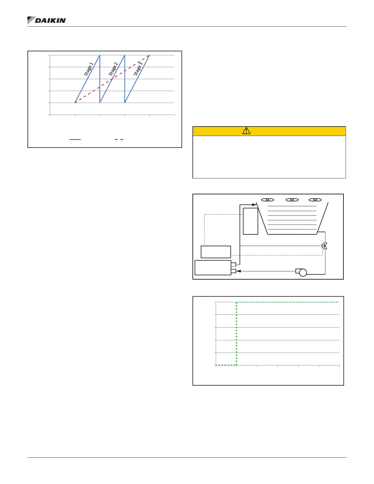
Figure 58: Strategy (I) VFD STAGE - VFD Speed vs. Temp
As shown in Figure 58, the default minimum and maximum
VFD speeds are 20% and 100%, respectively. These minimum
and maximum values are adjustable anywhere between 0%
and 100%. Additional fans stage on when the VFD speed
reaches the maximum value that was set.
Strategy (II) VALVE SP:
This control strategy is tower staging (up to three stages)
with a low-limit controlled bypass valve. The tower fans are
controlled as in method (I), plus a tower bypass valve is
controlled to provide a minimum condenser EWT. There is no
interconnection between the fan control and the valve control.
See Figure 59 and Figure 60.
To set up in HMI,
A. The TOWER Setpoint setting for Cooling Tower Control
strategy should be NONE. Tower Valve/VFD should be
changed to VALVE SP for control of the bypass valve
based on temperature or lift.
Tower Valve Type. Select NC or NO depending if valve
is normally closed to the tower with no control power or
normally open to the tower with no control power.
B. If TEMP was selected for Cooling Tower Control, set the
Valve Target Temperature - default is 65°F. This setpoint
is usually 5°F below the minimum fan stage setpoint
settings when TEMP is selected:
1. Set Valve Deadband - Temp. The default of 1.0°F is a
good place to start.
2. Set the Valve Control Range to the minimum position
to which the valve can go. The default is 10%.
3. Set the Valve Control Range to the maximum position
to which the valve can go. The default is 100%.
4. Set the Valve Control Error Gain. The default is 20.
5. Set the Valve Control Slope Gain. The default is 1.
F. If LIFT was selected for Cooling Tower Control, set
the Valve Target - Lift; default is 30 psi. This setpoint
is usually 5 psi below the minimum fan stage setpoint
7. Set Valve Deadband - Lift. The default of 1.0 psi is a
recommended initial setting.
8. Set the Valve Control Range to the minimum position
to which the valve can go. The default is 10%.
9. Set the Valve Control Range to the maximum position
to which the valve can go. The default is 100%.
10. Set the Valve Control Error Gain. The default is 20.
11. Set the Valve Control Slope Gain. The default is 1.
CAUTION
Valve Control Error Gain and Slope Gain setpoints are site
inputs. To avoid possible equipment damage, these setpoints
should be set by personnel experienced with setting up this
type of control.
Figure 59: Strategy (II) - VALVE SP
Figure 60: Strategy (II) VALVE SP - Valve Opening vs. Temp
As shown in Figure 60, the default temperature at which the
valve opens completely is 65°F. This temperature is the Valve
SP (also called Valve Target) and is adjustable.
0
20
40
60
80
100
65 70 75 80 85 90
VFD Speed (%)
Temperature (°F)
3 Fan Stages 1 Fan Stage
Condenser
Bypass Line
0-10 VDC Signal
Bypass
Valve
Cooling Tower
Fan Staging
(Up to 3 fans)
MicroTech
®
Controller
Tower
Control
Panel
0
20
40
60
80
100
60 65 70 75 80 85 90
Valve Opening (%)
Temperature (°F)