Piranha Color Camera User’s Manual 17
DALSA 03-032-10211-01 5/9/2007
greater than the required camera voltage. For example, to achieve +12V at the
camera, the power supply may need to be +12.5V or greater.
Protect the camera with a fast-blow fuse between power supply and camera.
Do not use the shield on a multi-conductor cable for ground.
Keep leads as short as possible to reduce voltage drop.
Use high-quality linear supplies to minimize noise.
Use an isolated type power supply to prevent LVDS common mode range
violation.
Note: Camera performance specifications are not guaranteed if your power supply
does not meet these requirements.
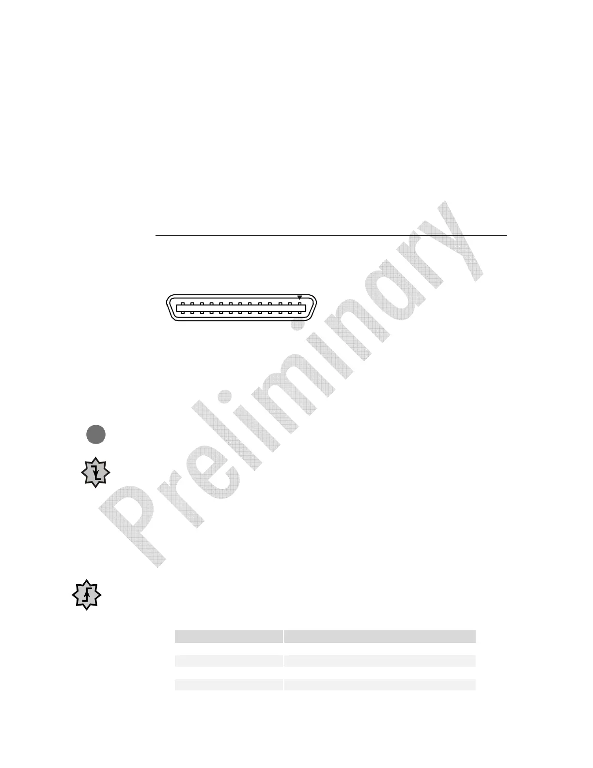
2.5 Camera Link Data Connector
Figure 3: Camera Link MDR26 Connector
MDR26 Female
1
14
13
26
Mating Part
: 3M 334-31 series
Cable:
3M 14X26-SZLB-XXX-0LC
**
Input Signals, Camera Link
The camera accepts control inputs through the Camera Link MDR26F connector.
The camera ships in internal sync, internal programmed integration (exposure mode 2).
EXSYNC (Triggers Line Readout)
Line rate can be set internally using the serial interface. The external control signal
EXSYNC is optional and enabled through the serial interface. This camera uses the
falling edge of EXSYNC to trigger pixel readout.
Direction Control
You control the CCD shift direction through the serial interface. With the software
command,
scd, you determine whether the direction control is set via software control
or via the Camera Link control signal on CC3.
Output Signals, Camera Link
These signals indicate when data is valid, allowing you to clock the data from the camera
to your acquisition system. These signals are part of the Camera Link configuration and
you should refer to the DALSA Camera Link Implementation Road Map, available at
http://vfm.dalsa.com/, for the standard location of these signals.
Clocking Signal Indicates
LVAL (high) Outputting valid line
DVAL (high) Valid data (unused, tied high)
STROBE (rising edge) Valid data
FVAL (high) Outputting valid frame (unused, tied high)
IMPORTANT:
This camera’s
data should be
sampled on the
rising edge of
STROBE.
i