Piranha Color Camera User’s Manual 19
DALSA 03-032-10211-01 5/9/2007
Base Configuration Timing
Each pixel output has 8 bits for each of the three colors (red, green, and blue)
Table 5: Base Configuration Video Data
Base Configuration
Connector 1 Maximum SSF
8
CLM
1
Bits
2
Taps
3
Lum
4
Time
5
Port
6
A Port B Port C SOT
7
2k60 4k60 2k80 4k80
40 19.0 9.7 19.0 9.7 5 8 3 No − R
0-7
G
0-7
B
0-7
80 22.7 12.0 32.4 17.7
T
0
R
0-7
B
0-7
− 9 8 3 Yes
T
1
G
0-7
Y
7-0
−
40 19.0 9.7 19.0 9.7
T
0
R
0-7
B
8-11
R
8-11
B
0-7
10 12 3 Yes
T
1
G
0-7
Y
8-11
G
8-11
Y
0-7
40 19.0 9.7 19.0 9.7
Notes:
1. CLM: Camera Link Mode
2. Bits: Number of bits per pixel
3. Taps: Number of camera link taps per color
4. Luminance: Indicates whether a fourth tap constructed from the RGB using SCC
command is output
5. Time: Time multiplex interval
6. Port : Camera Link port
7. SOT: Output throughput [mega-pixels / second / color]
8. Maximum SSF: Maximum line rate [kHz] possible in this mode (may be reduced by
SAH, ELS and SRM)
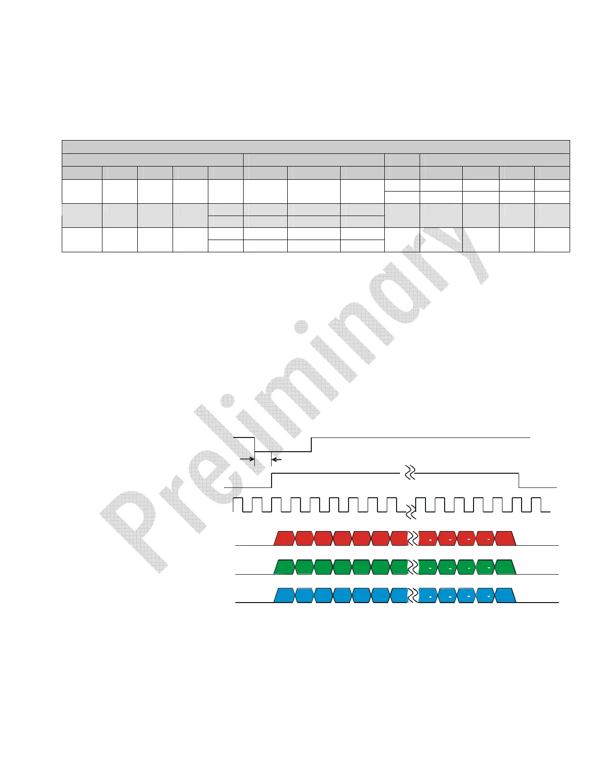
Figure 4: Base Configuration
EXSYNC
TBD
R1
R2
R3
R4
R5
R6
R7
Rn 1
Rn
Rn 2
Rn
3
Rn
4
G1
Gn 1
Gn
Gn 2
Gn 3
Gn 4
G2
G3
G4
G5
G6
G7
B1
Bn 1 Bn
Bn 2
Bn 3
Bn 4
B2
B3
B4
B5
B6
B7
RED Data
GREEN Data
BLUE Data
n = Number of pixels per line (2048 or 4096)
Data = 8 -bits/color/pixel
Line and Data Valid
Pixel Clock
40 or 80MHz