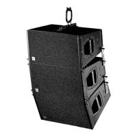
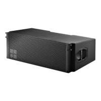
SUB columns
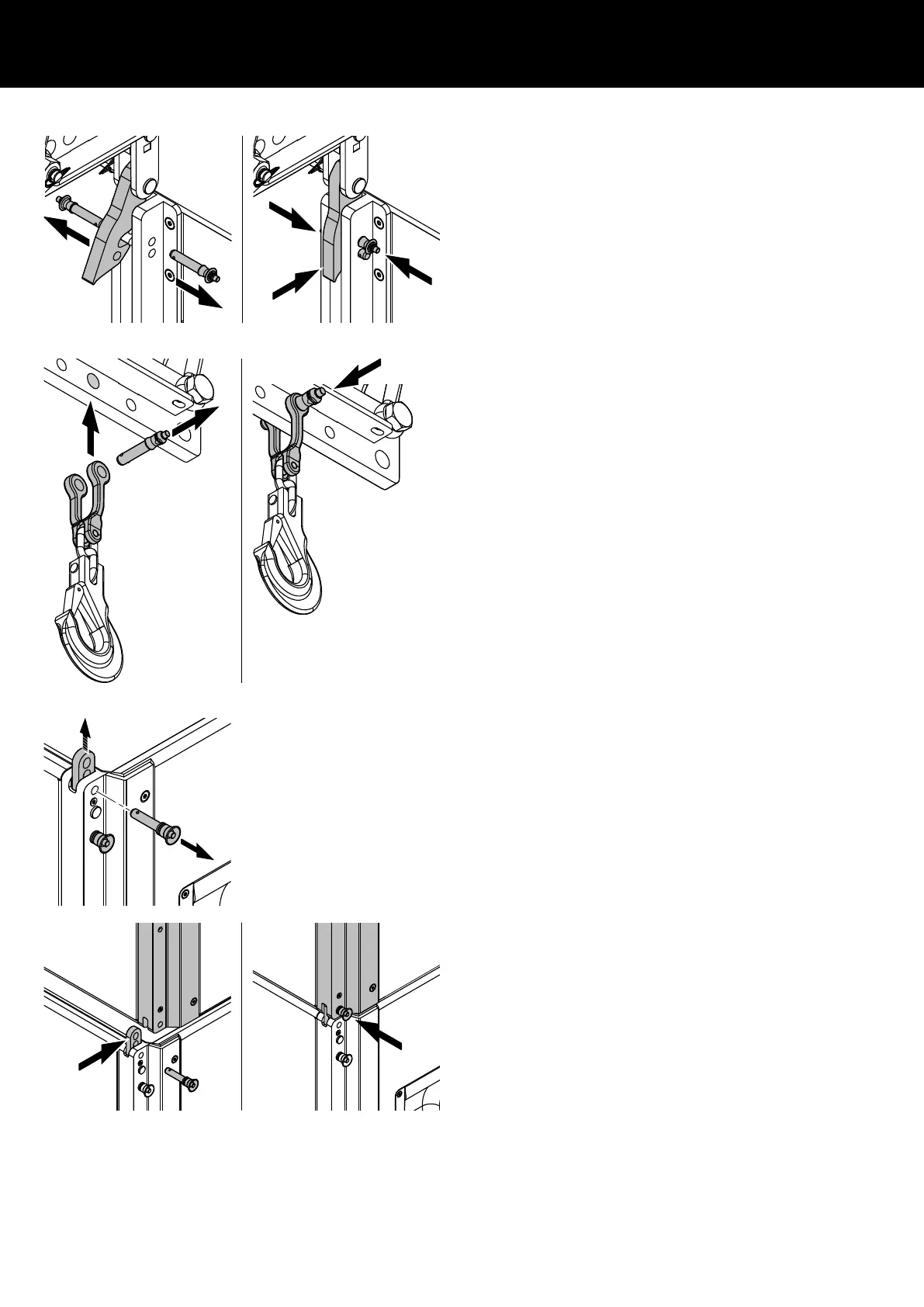
4. On the rear rigging strand, release both Locking pins.
5. Fold the Rear link into the rigging strand and reinsert the
Locking pins.
2. Attaching the cable pick (Z5713)
1. Release the Locking pin of the coupling shackle.
2. Attach the coupling shackle to the dedicated hole position at
the rear end of the load beam.
3. Reinsert the Locking pin and ensure the pin is fully inserted and
locked.
4. Set suitable lengths of the individual loudspeaker cables, and
attach split sets when applicable and connect the cables
subsequently during the entire setup procedure.
3. Attaching the next SUB assembly
1. Provided the SUB cabinets are interconnected by their Front
and Rear links as described in Þ Chapter 3.16.2 "E7492
Touring cart SL-SUB/SL-GSUB" Þ "Loading the cart" on page
39, lift the assembly out of the Touring cart to position the next
assembly below and put the cart aside.
2. Position the next Touring cart below and extend the Front links.
3. Lower the array onto the cabinet until the Front links of the
bottom cabinet fit into the slots of the upper cabinet.
4. Insert the second Locking pins of the cabinet's Front links on
both sides.
d&b SL-Series Rigging manual 1.10 en 61
 Loading...