SL-Series rigging modes - 2 in 1
The SL-Series rigging system allows for two different rigging modes:
▪ Tension mode,
▪ Compression mode,
▪ or a combination of both, depending on the array length and
the compression force required.
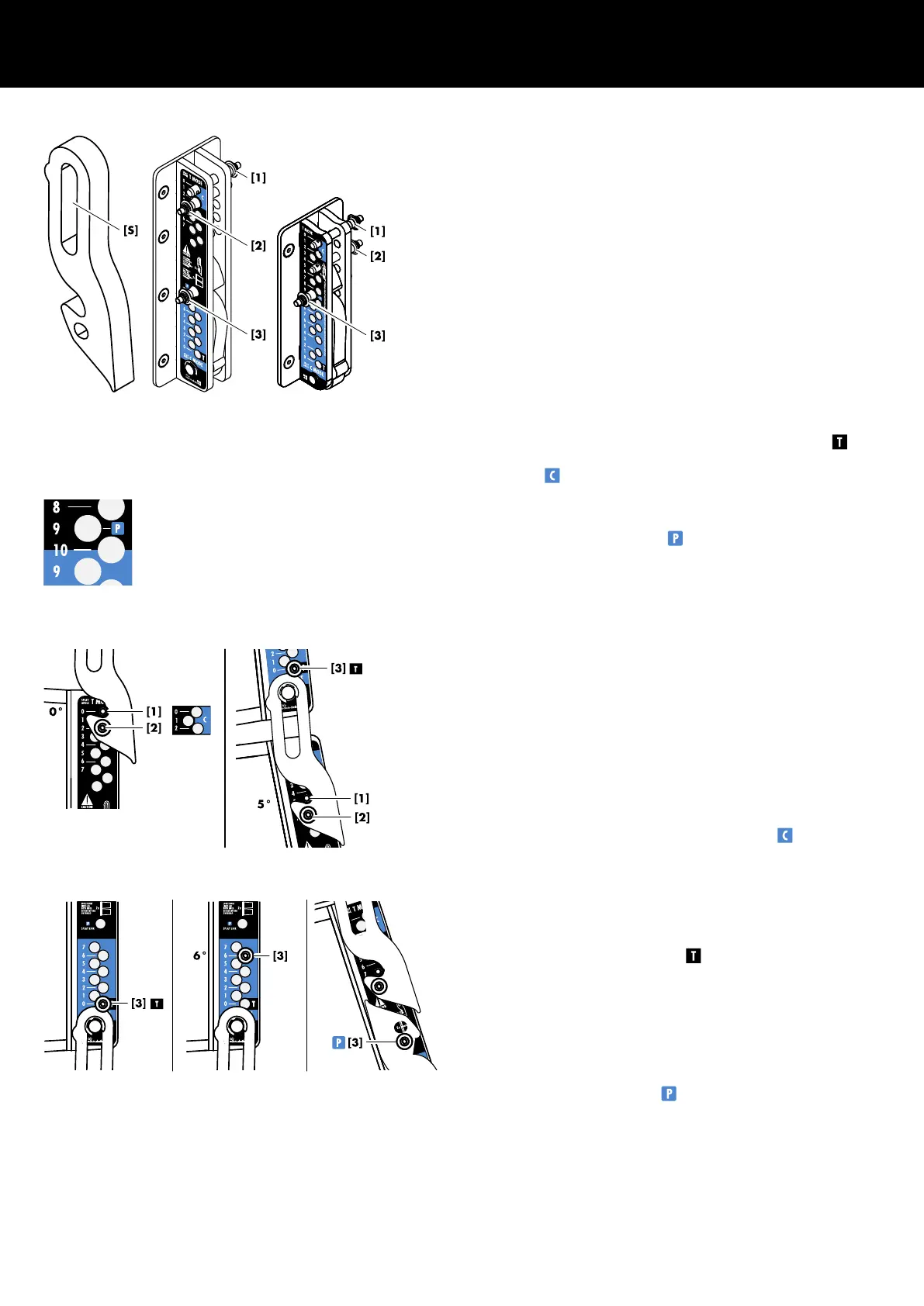
Rear rigging strand
Splay link, Locking pins and hole grids
The Splay link on the rear rigging strand of the SL-TOP cabinet is
equipped with a slotted hole [S] which allows for either Tension or
Compression mode setup without any further modification to the
cabinet.
For this purpose, the rear rigging strand provides three (3) Locking
pins and two dedicated hole grids. The bi-colored label (black/
blue on GSL8/KSL8 and black/grey on GSL12/KSL12 cabinets)
simplifies the assignment of the appropriate hole grid to the
respective rigging mode.
The top hole grid (black area) is used in Tension mode (Þ )
while the bottom hole grid (colored area) is used in Compression
mode (Þ ).
Note: On KSL8/KSL12 cabinets, the 10° hole is used for both
rigging modes, while the 9° hole of the Tension mode hole grid is
used to park the Splay link (Þ ).
Locking pin conventions
Pin [1]
Pin [2]
Tension mode:
In Tension mode, pin [1] is used to preset the
splay angle of a certain cabinet on the top hole
grid of the cabinet itself. During hoisting, the
Splay link of the upper cabinet will engage and
safety pin [2] is inserted in the hole directly
below.
Compression mode:
In Compression mode, pin [1] and safety pin [2]
are always inserted in the 0° / 2° holes of the
top hole grid of all cabinets (Þ
).
Pin [3] Tension mode:
In Tension mode, pin [3] is always inserted in the
0° hole of the bottom hole grid to fix the Splay
link in place (Þ ).
Compression mode:
In Compression mode, the splay angle between
two cabinets is set on the rear rigging strand of
the upper cabinet using pin [3].
Park position:
Pin [3] is also used to fix the Splay link in its park
position (Þ ), e.g. when the Splay link of the
last cabinet is in Tension mode.
Common hole on KSL8/KSL12 cabinets
Pin [1]/[2] convention
Tension and Compression mode
Pin [3] convention
Tension, Compression mode and Park position
2 SL-Series rigging modes - 2 in 1
d&b SL-Series Rigging manual 1.10 en 7
 Loading...