SL-Series rigging modes - 2 in 1
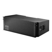
Pin [3] Compression frame:
In Compression mode the compression frame is
attached below the last cabinet of the array. In
this case, pin [3] is always inserted in the 0°
hole of the bottom hole grid (Þ ).
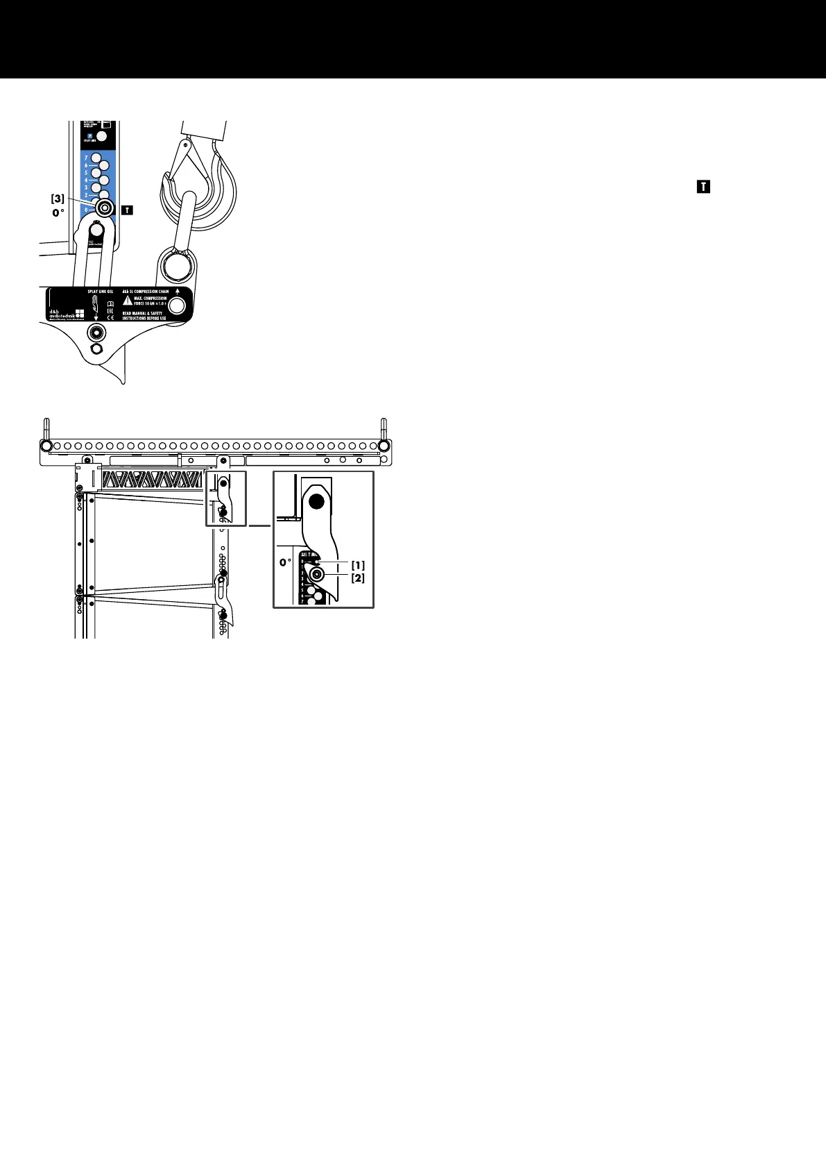
First cabinet to frame
For both, Tension and Compression modes, the Splay link of the
flying frame is always engaged in the 0° hole of the top hole grid
of the first cabinet using pin [1] and safety pin [2].
Overview charts
The following charts provide an overview of the rigging mode
principles of the GSL system at one glance.
The same principles also apply to the KSL system.
d&b SL-Series Rigging manual 1.10 en8
 Loading...