Sub
CF2
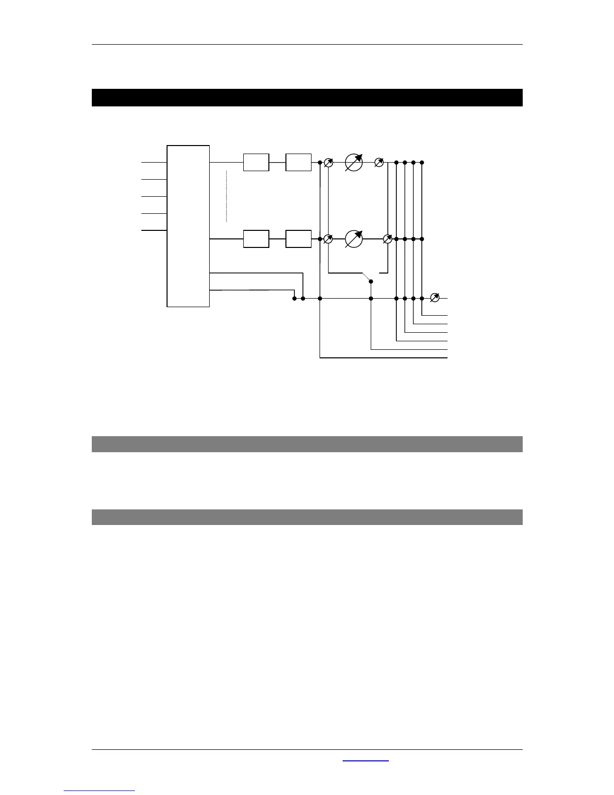
Dedicated Analog Outputs
Phones/Analog 7/Digital outputs 1-7
and Cobranet outputs 1/2-31/32 can
select one of the (buss)outputs (or
in
ital 1..7
MIC 1..4
St Line1..4, 7
Cobra 1/2..31/32
CUE
Figure 1: Audio Signal Flow
5.1 Input matrix
To give you the flexibility you need in your applications the Lyra has a full matrix before processing takes
place. You can assign one of your inputs to the eight modules in any way you want. Furthermore you can
bring one of the inputs to the external inputs to make them available at the CRM buss.
5.2 Buss structure
As mentioned before, every module features EQ- and dynamic processing. This is why these channels are
often referred to as ‘processing’ channels.
The output of the 8 stereo audio processing channels can be routed to different busses.
Busses that are available are:
• Stereo program buss.
• Stereo sub buss.
• Stereo aux. buss.
• Stereo CUE buss.
• Automatic Mono Cleanfeed 1
• Automatic Mono Cleanfeed 2
The 6 CRM sources (Prog, Sub, Aux, CUE, Extern 1, Extern 2) may be summed into the CRM buss.