Hardware Connections
Lyra Digital Mixer from D&R Phone +31 294 418014, email: info@d-r.nl Page 20
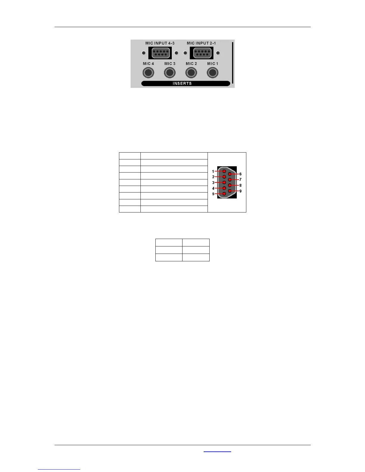
Figure 7: Microphone inputs at rear side
The MIC connections on the backside of the 19” rack are parallel with the XLR connections at the front
side of the 19” rack.
Warning: Phantom power is also applied to these connectors. (Don't short pins while phantom power is
on.)
At the back side you can find the four microphone inserts on a jack type connector.
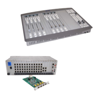
Pin 1 Mic IN 1 +
Pin 6 Mic IN 1 -
Pin 2 GND
Pin 7 Mic IN 2 +
Pin 3 Mic IN 2 -
Pin 8 GND
Pin 4 Not Connected
Pin 9 Not Connected
Pin 5 Not Connected
Table 2: Pinning MIC Input 4-3 and MIC Input 2-1
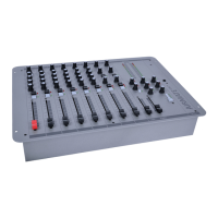
Tip Return
Ring Send
Sleeve GND
Table 3: Pinning Inserts