Hardware Connections
Lyra Digital Mixer from D&R Phone +31 294 418014, email: info@d-r.nl Page 25
9.3 Global Inputs/Outputs
9.3.1 GPIOs
The in-/outputs can be used for global functionality for example synchronization, remote function, relay
logic etc…
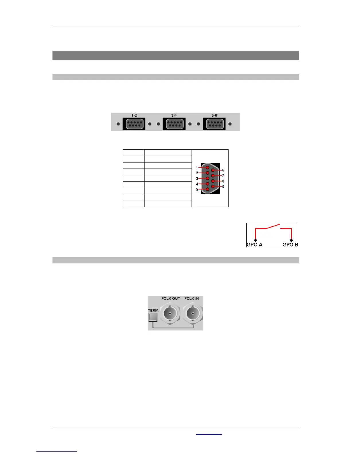
Each Sub-D connector represents 2 GPIO's.
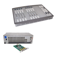
Figure 14: GPIO connections at rear side
Pin 1 GPO 1 A
Pin 6 GPO 1 B
Pin 2 Not Connected
Pin 7 GPO 2 A
Pin 3 GPO 2 B
Pin 8 Not Connected
Pin 4 GPI 1
Pin 9 GPI 2
Pin 5 Ground
Table 7: Pinning GPIO's
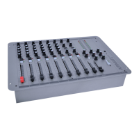
GPO-A and GPO-B make connection if the GPO is activated!
Maximum current: 200 mA
Maximum resistance when connection made: 12 Ohm
Maximum Voltage: 24 V
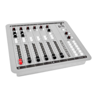
9.3.2 Word clock in and out.
On the rear side of the Lyra you can find two BNC connectors with the text FCLK OUT and FCLK IN.
These are the word clock in/out connection which can be used for synchronization purposes.
If the Lyra is the last in the synchronization chain, you can use the TERM. switch to terminate the line. (75
Ohm Termination)
Figure 15: Word Clock In and Out at rear side